For more in-depth info than is covered here, look at the following:
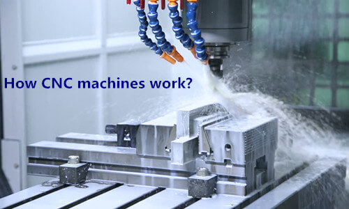
CNC basics
To better understand the problems involved to successfully use your Rhino data for a CNC-controlled machining or cutting type operation, you need to understand the CNC process and how it works. Hopefully, this little primer will help.
First, a couple of definitions
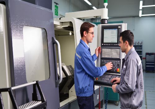
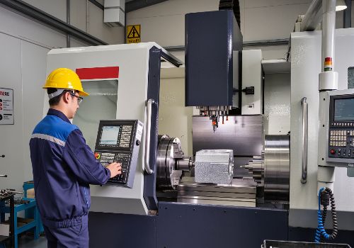
CNC – Computer Numerical Control – Taking digitized data, a computer and CAM program is used to control, automate, and monitor the movements of a machine. The machine can be a milling machine, lathe, router, welder, grinder, laser or waterjet cutter, sheet metal stamping machine, robot, or many other types of machines. For larger industrial machines, the computer is generally an on-board dedicated controller. But for more hobbyist types of machines, or with some retrofits, the computer can be an external PC. The CNC controller works together with a series of motors and drive components to move and control the machine axes, executing the programmed motions. On the industrial machines there is usually a sophisticated feedback system that constantly monitors and adjusts the cutter’s speed and position.
Desktop CNC – There are many smaller modelmaker-hobbyist style desktop CNC machines. In general these are lighter weight, less rigid, less precise, slower, and less expensive than their industrial counterparts, but can do well for machining objects out of softer materials such as plastics, foam, and wax. Some desktop machines may run a lot like a printer. Others have their own closed command system and perhaps even dedicated CAM software. A few will also accept standard G-code as input. Some industrial standard desktop machines do exist with dedicated controllers for doing precise small work.
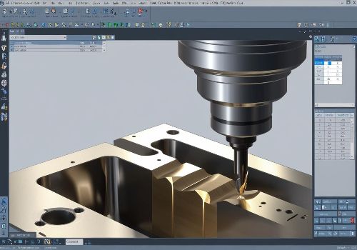
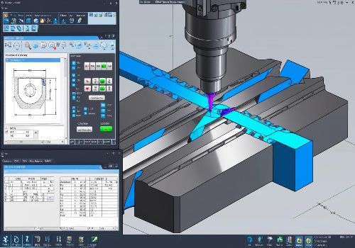
CAM – Computer Aided Machining or Manufacturing – Refers to the use of various software packages to create toolpaths and NC code to run a CNC controlled machine, based on 3D computer model (CAD) data. When the two are used together, this is generally referred to as CAD/CAM.
Note: CAM does not actually run the CNC machine, but just creates code for it to follow. It is also not an automatic operation that imports your CAD model and spits out the correct NC code. CAM programming, like 3D modeling, requires knowledge and experience in running the program, developing machining strategies, and knowing what tools and operations to use in each situation to get the best results. While there are simple programs that for the inexperienced user to get started without too much difficulty, more sophisticated models will take an investment in time and money to become proficient.
NC code – A special relatively simple computer language that a CNC machine can understand and execute. These languages were originally developed to program parts directly at the machine keyboard without the aid of a CAM program. They tell the machine what moves to execute, one by one, as well as controlling other machine functions such as spindle and feed speeds, coolant. The most common language is G-code or ISO code, a simple alphanumeric programming language developed for the earliest CNC machines in the 70s.
Postprocessor – While G-code is considered the standard, each manufacturer can modify certain parts such as auxiliary functions, creating a situation where G-code made for one machine may not work for another. There are also many machine manufacturers, such as Heidenhain or Mazak, that have developed their own programming languages. So, to translate the CAM software’s internally calculated paths into specific NC code that the CNC machine can understand, there is a bridge software piece software called a postprocessor. The postprocessor, once configured correctly, outputs the appropriate code for the chosen machine, so that in theory at least, any CAM system can output code for any machine. Postprocessors may be free with the CAM system or added cost extras.
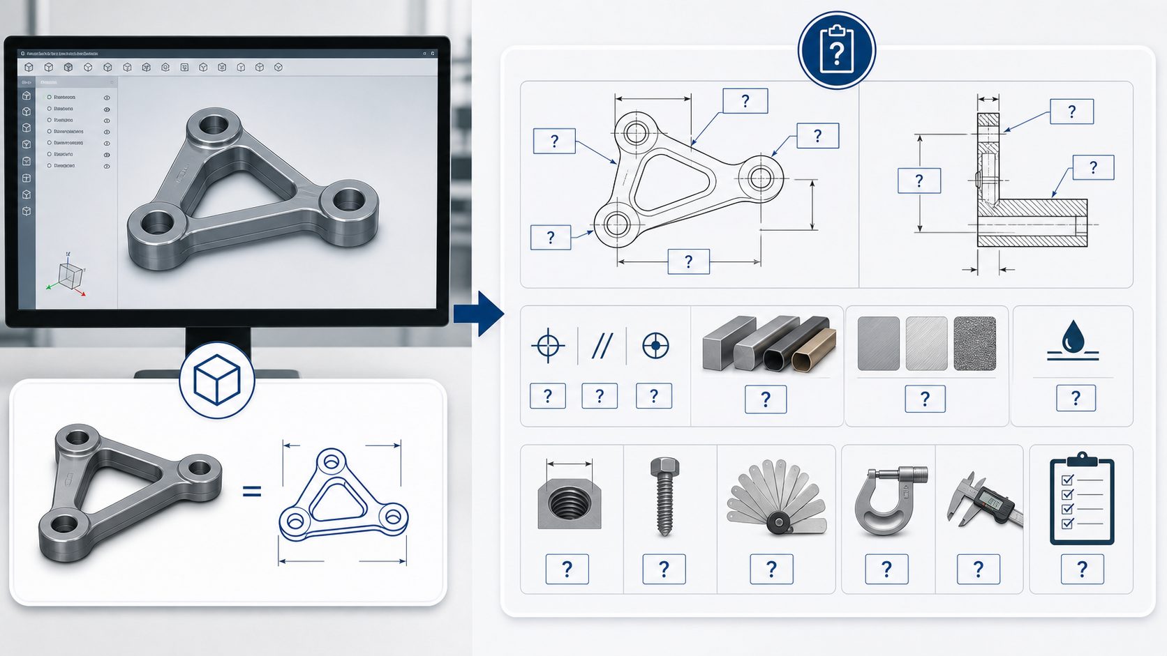
Here is a summary of the steps required to get a digital model to a CNC milling machine.
CNC controlled machines, general
CNC machines can have several axes of movement, and these movements can be either linear or rotary. Many machines have both types. Cutout machines like lasers or waterjets generally have just two linear axes, X and Y. Milling machines usually have at least three, X, Y, and Z, and can have more rotary axes. A five axis milling machine is one that has three linear axes and two rotary, allowing the cutter to operate in a full 180º hemisphere and sometimes more. Five axis lasers exist as well. A robot arm might have more than five axes.
Some limitations of CNC controlled machines
Depending on their age and sophistication, CNC machines can be limited to the capabilities of their control and drive systems. Most CNC controllers only understand straight line movements and circular arcs. In many machines, the arcs are restricted to the principal XYZ planes as well. Rotary axis movements can be considered like linear movements, just degrees instead of distance. To create arc movements or linear movements that are at an angle to the principal axes, two or more axes must interpolate (move precisely in a synchronized manner) together. Linear and rotary axes can also interpolate simultaneously. In the case of five axis machines, all five must be perfectly synchronized – no easy task.
The speed at which the machine controller can receive and process the incoming data, transmit commands to the drive system, and monitor the machine’s speed and position is critical. Older and less expensive machines are obviously less capable in this, much in the same way that an older computer will work less well and more slowly (if at all) on demanding tasks than a newer one.
Interpret your 3D and spline data first
A typical problem is how to set up your files and do your CAM programming so that the machine executing your parts will work smoothly and efficiently with the data. Since most CNC controls only understand arcs and lines, any form that is not describable with these entities needs to be converted into something usable. Typical things that need converting are splines, i.e. general NURBS curves that are not arcs or lines, and 3D surfaces. Some desktop machine systems are not able to understand circular arcs either, so everything must be converted into polylines.
Splines can be broken up into a series of line segments, a series of tangent arcs, or a combination of both. You can imagine the first option as a series of chords on your spline, touching the spline on each end and having a certain deviation in the middle. Another way is to convert your spline into a polyline. The fewer segments you use, the coarser the approximation will be, and the more faceted the result. Going finer increases the smoothness of the approximation, but also dramatically increases the number of segments. You can imagine that a series of arcs might be able to approximate your spline within tolerance with fewer, longer pieces. This is the main reason for preferring arc conversion over simple polyline conversion, especially if you are working with older machines. With newer ones, there is less of a problem.
Imagine surfaces as the same kind of spline approximation, just multiplied many times in the across direction with a space between (usually called the stepover). In general, surfaces are done using all line segments, but there are situations where arcs or a combination of lines and arcs can also be used.
The size and number of segments are determined by the accuracy required and the method chosen, and will directly influence the execution. Too many short segments will choke some older machines, and too few will make a faceted part. The CAM system is usually where this approximation is done. With a skilled operator who knows what the user needs and the machine can handle, it is usually no problem. But some CAM systems may not handle splines or certain types of surfaces, so you might need to convert the entities in the CAD software first (Rhino) before going into CAM. The translation process from CAD to CAM (via a neutral format such as IGES, DXF, etc.) may also occasionally cause problems, depending on the quality of the import/export functions of the programs.
Common conventions used in describing CNC procedures
Your project can be:
2 Axis if all the cutting takes place in the same plane. In this case, the cutter does not have any capability of movement in the Z (vertical) plane. In general the X and Y axes can interpolate together simultaneously to create angled lines and circular arcs.
2.5 Axis if all the cutting takes place entirely in planes parallel to the principal plane but not necessarily at the same height or depth. In this case, the cutter can move in the Z (vertical) plane to change levels, but not simultaneously with the X,Y movements. An exception might be that the cutter can interpolate helically, that is, do a circle in X,Y while moving simultaneously in Z to form a helix (for example in thread milling).
A subset of the above is that the machine can interpolate any 2 axes together simultaneously, but not 3. This does make a limited number of 3D objects possible, by cutting in the XZ or YZ planes, for example, but is much more limited than full 3 axis interpolation.
3 Axis if your cutting requires simultaneous controlled movement of the X,Y,Z axes, which most free-form surfaces require.
4 axis if it includes the above plus 1 rotary axis movement. There are two possibilities: 4 axis simultaneous interpolation (also known as true 4th axis). Or just 4th axis positioning, where the 4th axis can reposition the part between 3 axis operations, but does not actually move during the machining.
5 axis if it includes the above plus 2 rotary axis movements. Besides true 5 axis machining (5 axes moving simultaneously while machining), you also often have 3 plus 2 or 3 axis machining + 2 separate axes positioning only, as well as in rarer cases 4 plus 1 or continuous 4 axis machining + a single 5th axis positioning only. Complicated, isn’t it…
The article is cited from: https://wiki.mcneel.com/rhino/cncbasics