The plane machining with CNC machining center refers to the milling, drilling, reaming, boring and other machining processes on the plane workpiece; the three-dimensional machining refers to the processing of the solid surface under the control of the interpolation function of the CNC system of the machining center. The machining objects include complex curved workpieces and contoured contour workpieces. When carrying out these two processes these by machining centers, the machining tools and machining processes used are different, specifically the following.
Plane processing characteristics
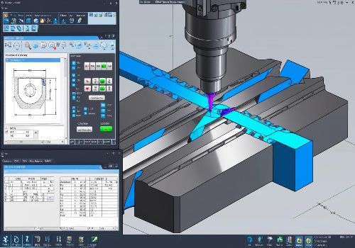
Compared with surface machining, plane machining with machining centers is relatively simple in terms of machining difficulty and programming difficulty. Typical plane machining includes both cavity machining and contour machining.
Cavity machining is the processing of flat-bottomed parts with closed boundary contours. It includes both machining of cavity area and contouring process, which is usually processed by end mills or forming tools. It is divided into two steps. The first step is to cut the inner cavity. The two main paths are circular cutting and row cutting. Whether it is circular cutting or row cutting, the common point is to ensure the entire cavity area is cut clean, no dead angle, no contours can be damaged, and the overlap of repeated passes should be minimized. The second step is to cut the contour, which is usually divided into roughing and finishing.
Using the machining center to milling plane profile, it should choose a reasonable infeed and retract position, and choose as much as possible in a less important position. Whether machining the outer contour or the inner contour, the tool must be arranged to enter the contour from the tangential direction, thus avoiding the tool leaving tooling marks at the entry point.
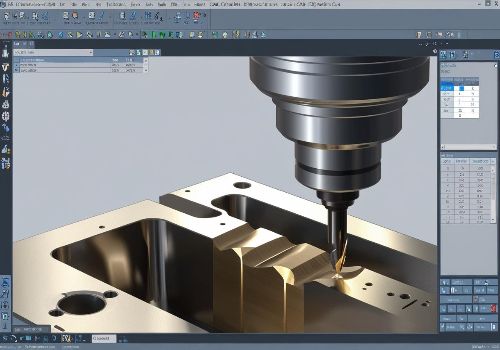
Three-dimensional processing characteristics
As the industry continues to evolve, the need for machining of complex curved surfaces and shaped parts is increasing. Such parts not only have to meet the standard of shape accuracy, but also put forward high requirements on the surface quality. Therefore, when processing such parts, the machining center used must have the function of three-dimensional movement.
The feed system of the machining center, with the interpolation function of the numerical control system, can perform multi-axis linkage machining to realize the three-dimensional curve movement of the tool. Therefore, in the case of such a complicated part, the processing can be completed at the fastest speed according to the setting of the program.
It should be noted that the surface machining should make a reasonable choice of the tool. Operators need to take into account different aspects of surface shape, tool shape and machining accuracy requirements, and use different milling methods. Processing tools commonly used for three-dimensional machining include ball-end tools, end mills, drum-like tools, and forming tools. The usual processing method is the row cutting method. This method allows the tool axis to remain constant throughout the machining process and parallel to the z-axis. The three-coordinate surface machining is realized by the three coordinates of x, y and z of the machining center, which are realized by walking tools.