In order to help freshman to learn mechnical drawing quickly, we’d like to share the post for your reference. Definitely Worth Collecting.
Mechanical Drawing Foundation
- The function and content ofpart drawing
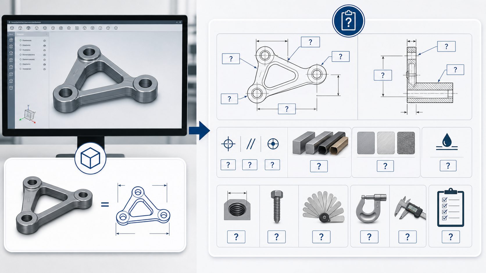
- The functionof part drawing: Part working drawing is the basis for manufacturing and testing parts, which according to the position and function of the parts in the machine, make the requirements for the parts of the shape, structure, size, materials and technical data and others.
- Part drawing contents: title bar, a group of graphics, the necessary size, technical requirements
- Technical requirements in part drawing
- Tolerance and fit
Tolerance: Reflect the accuracy requirements of parts
Fit: Reflect the elastic relationship between the parts.
<1>Dimensional tolerances
① Dimension – Indicates the value of the linear dimension value in specific unit
② Base size – Through it, applied to the upper and lower deviations, and calculate the limit size
③ Actual size – obtained size by measuring
④ Limit size – A hole or shaft allows the size of the two extremes, the larger one is called the maximum limit size, the smaller one is called the minimum limit size
⑤ Size deviation – it has upper deviation and lower deviation, he maximum limit deviation minus the basic size will get the algebraic difference, which called upper deviation; the minimum limit deviation minus the basic size will get the algebraic difference which called lower deviation; upper deviation and lower deviation are collectively called limit deviation, the deviation can be positive, negative or 0
⑥ Dimensional tolerance – Maximum limit size minus minimum limit size. It is the amount of change allowed by size. Dimension tolerance is always positive
⑦ Zero line – A straight line in the limit and fit diagram which representing the basic size
⑧ Standard tolerance – National standards for a certain basic size, the standard tolerance has 20 tolerance level
<2>Fit
Fit has three types: clearance fit, interference fit and transition
<3>Markings for tolerance and fit
① There are three forms of dimension tolerance in the part drawing
- Mark the tolerance code
- Mark the limit deviation
- Mark tolerance code and limit deviation both
② Generally, in assembly drawing, it will mark linear dimension fit code or mark hole and shaft limit deviation value separately.
- Surface roughness
Surface roughness refers to the micro-geometrical properties on the part surface which be made up of smaller peak and valley
National standard specify three mainly parameters of the surface roughness: Ra,Rz,Ry
In general, we often take Ra as surface roughness.
Note: Above information is just for reference only.
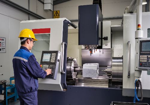
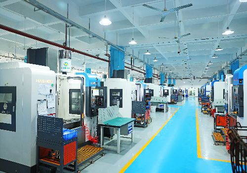
We offer CNC Machining, Metal Stamping, Metal fabrication services, if you have project need support, contact us today.