Preventing chatter in CNC machining requires a systematic approach that combines optimal machine setup, strategic tool selection, precise cutting parameters, and sometimes advanced detection systems. By understanding the root causes of regenerative vibration and implementing proven countermeasures, machinists can eliminate the “screaming” that destroys surface finishes, shortens tool life, and compromises part quality.
Introduction: Understanding the Enemy—What Is Chatter?
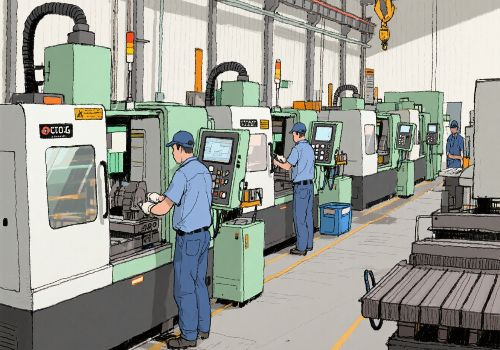
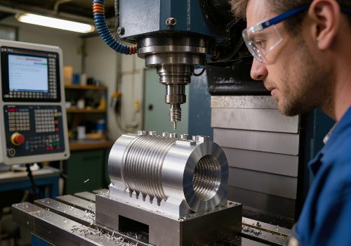
If you’ve ever heard your CNC machine emit a loud, screaming sound during a cut—accompanied by visible wavy lines on your workpiece—you’ve experienced chatter. But chatter is far more than just an annoying noise. It is a self-excited vibration that feeds on itself, much like the feedback loop on a loudspeaker system that creates those terrible screeching sounds .
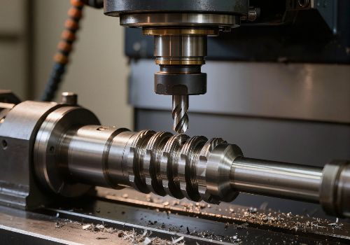
When a cutting tool vibrates, it leaves a wavy surface behind. On the next revolution or pass, the tool encounters those waves, causing the cutting force to vary, which in turn intensifies the vibration. This regenerative cycle creates a distinctive chatter pattern on the workpiece and can rapidly destroy cutting tools, damage machine spindles, and ruin expensive parts .
The stakes are high: chatter not only ruins surface finish but dramatically reduces tool life and can even shorten the life of your CNC machine tool itself . Fortunately, chatter is predictable and preventable with the right strategies.
The Foundation: Maximizing Rigidity and Stability
Tool Stickout: The 10% Rule
The single most impactful factor in chatter prevention is tool rigidity, and nothing affects rigidity more than tool stickout. Longer tools deflect more easily, creating the perfect conditions for chatter. The relationship is dramatic: a 10% reduction in tool length results in approximately 25% increase in tool stiffness .
For milling operations, a good rule of thumb is to keep tool stickout to no more than 3 times the tool diameter unless absolutely necessary . For boring bars, the material matters: steel boring bars remain stable up to a stickout of 3 times diameter, while carbide bars can extend to 5 times diameter . When extreme reach is unavoidable, special vibration-dampening boring bars are available.
Workholding Integrity
A loose workpiece guarantees chatter. Ensure your workholding is absolutely secure:
-
For vises and fixtures: Verify that clamping forces are adequate and evenly distributed
-
For lathe chucks: Ensure jaws are properly bored to match the workpiece diameter, and check for gaps between the workpiece and jaws using a 0.001″ feeler gauge
-
For thin-walled parts: Use climb milling to direct cutting forces in a way that minimizes energy transfer to the part
-
For long parts in lathes: If the unsupported length exceeds 3 times the diameter, use a tailstock. For ratios above 10:1, consider a steady rest.
Machine Foundation
Your CNC machine itself must sit on a solid foundation. A single continuous slab of reinforced concrete is required—machines straddling multiple slabs or sitting on cracked foundations will never achieve chatter-free performance.

Cutting Parameters: Finding the Sweet Spot
The Chip Load Balancing Act
One of the most common causes of chatter is too light a chip load. When RPM is too high or feed rate too low, the tool rubs rather than cuts. This rubbing generates heat, accelerates wear, and creates resonance that leads to chatter .
The fix: increase feed rate or decrease spindle speed to achieve proper chip thickness. Many machinists instinctively slow down when they hear chatter, but sometimes speeding up works better because it changes the vibration frequency away from the resonant peak.
Spindle Speed Tuning
Chatter is a resonant phenomenon, meaning certain spindle speeds will excite vibration while others will not. If you encounter chatter:
-
Try increasing spindle speed 5-10% first
-
If that doesn’t work, try decreasing by 5-10%
-
Continue making small adjustments until you find a stable “sweet spot”
This works because changing RPM shifts the frequency at which the tool teeth strike the material, potentially moving you out of a resonant condition.
Depth of Cut Strategies
Axial and radial depth of cut significantly influence stability. For roughing operations:
-
Use High Efficiency Milling (HEM) / Adaptive toolpaths that maintain constant tool engagement and eliminate force spikes that trigger vibration
-
Reduce radial engagement to lower cutting forces, but be careful not to go so low that you cause rubbing
-
Consider the “axial contact points” principle—finding the right axial depth that corresponds to stable cutting conditions based on your tool’s helix pitch.
Tooling Selection and Geometry
Flute Count and Configuration
The number of flutes and their spacing dramatically affect chatter behavior:
-
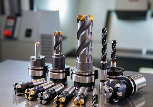
Variable helix and unequal flute spacing tools are specifically designed to disrupt harmonic vibrations . These tools break up the regular pattern of tooth impacts that can build into resonance.
-
More flutes generally provide smoother cutting because more flutes are engaged simultaneously, stabilizing the cut . However, too many flutes can cause chip packing issues in materials like aluminum.
-
For severe chatter problems, consider single-flute cutters or removing inserts from indexable tools to change the vibration frequency.
Tool Coatings and Geometry
-
High helix angles reduce radial cutting forces and improve chip evacuation in materials like aluminum
-
Positive rake inserts lower cutting forces and improve stability
-
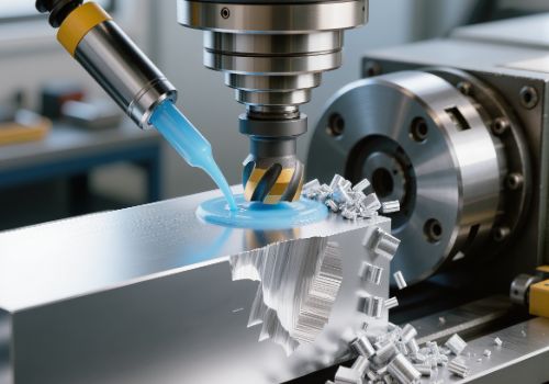
Polished flutes reduce friction and material adhesion in sticky materials like stainless steel and aluminum
-
Larger core diameters increase tool rigidity and resistance to deflection.
Corner Machining Considerations
Chatter frequently occurs when machining corners due to increased tool engagement. Strategies to address this:
-
Use a tool with a smaller diameter than the corner radius to keep the tool moving continuously
-
Use circular interpolation to create a larger corner radius than specified, then finish with a smaller tool
-
Ensure tool radius is slightly smaller than the minimum part radius to prevent the tool from stopping and re-engaging.

Advanced Tooling and Techniques
Specialized Chatter-Resistant Tools
-
Roughing end mills with serrated edges can radically change cutting dynamics
-
Button cutters (copy mills) convert cutting forces to the axial direction, which is the stiffest direction of cut
-
Vibration-dampening boring bars use tuned mass absorbers to eliminate chatter in deep bores
Tool Tuning
Changing tool stickout by as little as 0.100″ (2.5mm) can shift the tool’s natural frequency enough to eliminate chatter . While shorter stickout is generally better for rigidity, sometimes a slightly longer stickout that moves you away from a resonant frequency can actually solve chatter problems.
Runout Management
Excessive tool runout causes uneven chip loads, with one flute doing more work than others. This imbalance amplifies vibration. Aim for ≤0.0002″ (0.005mm) runout at the tool tip, using high-precision collet chucks or shrink-fit holders . Check holders regularly for wear, debris, or damage.
Material-Specific Considerations
Different materials present unique chatter challenges and require tailored approaches:
Aluminum
-
Use high helix, polished flutes for excellent chip evacuation
-
Watch for chip packing—tools designed for efficient evacuation are essential
-
High speeds are effective, but tool rigidity still matters
Stainless Steel
-
Work-hardens quickly, creating tougher cutting conditions
-
Requires strong geometries (lower helix, positive rake) and excellent chip control
-
Coolant is essential—use through-coolant tools to manage heat
Titanium
-
Prone to chatter due to low thermal conductivity and elasticity
-
Use low radial engagement with high axial depth (adaptive milling is key)
-
Sharp tools degrade fast—look for edge prep and coatings that handle heat
-
Thin walls are problematic; focus on better cooling and reduced engagement
Cast Iron
-
Generally low risk for chatter, but vibration can still occur with unstable setups
-
Use rigid setups and consistent feed rates to avoid tool bounce in interrupted cuts
Inconel / Nickel Alloys
-
Tough, work-hardening, poor heat dissipation
-
Needs low stepovers, steady engagement, and coated tools
-
Run slower but maintain aggressive feed per tooth to avoid rubbing

Advanced Detection and Suppression Systems
Modern Chatter Detection Technology
Recent advances have produced sophisticated chatter detection systems integrated directly into CNC controls. A 2025 study published in Precision Engineering describes a lathe spindle equipped with displacement sensors that communicate with the CNC control to detect chatter vibrations in real-time .
These systems use algorithms based on multiple samples per revolution to calculate chatter indicators. When chatter is detected, an autonomous algorithm adjusts spindle speed based on the natural frequency determined from the chatter vibration frequency.
Sensor-Less Approaches
Researchers have also developed methods using existing machine data:
-
Spindle motor current command extracted from the CNC can detect chatter without additional sensors
-
Axis encoder feedback can be analyzed to identify chatter energy and automatically manipulate spindle speed
Stability Lobe Diagrams
For those wanting to take chatter prevention to the scientific level, Stability Lobe Diagrams plot the boundary between stable and unstable cutting conditions across different spindle speeds . These diagrams reveal “sweet spots”—specific RPM ranges where you can take significantly deeper cuts without chatter.
While determining these lobes traditionally required complex modal analysis, modern software tools like G-Wizard can help machinists optimize cut parameters to stay within stable regions.
Practical Troubleshooting Guide
When you hear chatter, use this systematic approach:
| If You See/Hear… | Likely Cause | Adjust This |
|---|---|---|
| Loud screaming, visible waves | System resonance | Adjust spindle speed ±5-10% |
| Squealing on light cuts | Chip load too light | Increase feed or reduce RPM |
| Chatter in corners | Excessive engagement | Use smaller tool, reduce stepover, or adjust corner radius strategy |
| Vibration in deep pockets | Tool too long | Shorten stickout, use stub-length tool, reduce depth of cut |
| Random vibration, poor finish | Workpiece movement | Check clamping, tailstock support, jaw contact |
| Chatter only on finishing passes | Tool deflection | Reduce radial engagement, check runout, use sharper tool |

Quick Reference: Chatter Prevention Checklist
Setup Checklist
-
Tool stickout minimized (≤3× diameter if possible)
-
Workpiece securely clamped with full jaw contact
-
Tailstock used for parts exceeding 3:1 length-to-diameter ratio
-
Machine on solid, continuous concrete foundation
-
Tool holder clean and in good condition
Tooling Checklist
-
Tool sharp and appropriate for material
-
Variable helix or unequal flute spacing for harmonic disruption
-
Runout measured and ≤0.0002″ at tip
-
Correct number of flutes for the application
-
For indexable tools: clean pockets, proper insert seating
Parameter Checklist
-
Chip load adequate (not rubbing)
-
Spindle speed tuned away from resonant frequencies
-
Radial engagement appropriate (not too high, not too low)
-
Adaptive toolpaths used for constant engagement
-
Coolant properly aimed and at correct concentration
Conclusion: Chatter Is a Signal, Not a Mystery
Chatter is more than just an inconvenience—it’s a signal that something in your machining system is out of balance. But with the right knowledge and systematic approach, it’s entirely controllable .
The most successful machinists view chatter prevention holistically: start with a rigid setup, choose tools designed for stability, optimize cutting parameters systematically, and use modern detection tools when available. By addressing the root causes rather than just treating symptoms, you can achieve smoother operations, longer tool life, better surface finishes, and higher productivity.
Remember: every machine, every tool, and every material has its sweet spot. Finding that spot is what separates just getting by from running smoothly, quietly, and efficiently.