Preventing tool breakage in CNC machining requires a systematic approach that combines proper tool selection, optimized cutting parameters, rigid machine setup, and proactive monitoring. Understanding the specific failure modes and their root causes is the first step toward implementing effective prevention strategies.
Introduction: The High Cost of Broken Tools
Every machinist knows that dreaded sound—the sharp “tink” of a cutting tool failing mid-operation. Beyond the immediate frustration, tool breakage carries significant costs: scrapped parts, machine downtime, replacement tooling expenses, and potential damage to your CNC equipment. In high-volume production, these costs multiply rapidly.
The good news is that tool breakage is rarely random. Most failures follow predictable patterns with identifiable root causes. By understanding these patterns and implementing systematic prevention strategies, you can dramatically reduce tool breakage, improve part quality, and maximize your machining profitability.
Understanding Tool Failure Modes
Before preventing tool breakage, you must recognize how tools fail. Tool failure falls into two main categories: wear-related failure (gradual degradation) and breakage-related failure (catastrophic fracture)
Common Tool Breakage Patterns
Cutting Edge Chipping
Small fragments breaking from the cutting edge, often visible as jagged chips near the nose radius. This typically occurs due to vibration, excessive tool overhang, weak clamping, or an edge preparation too sharp for the load. Chipping often accelerates at shoulders and interruptions where the tool experiences sudden changes in chip thickness.
Corner Fracture or Impact Break
A clean corner break, often occurring at a shoulder or exit point. This signals aggressive engagement, sharp toolpath transitions, or interrupted cut shock. The tool encounters a load spike it cannot withstand.
Catastrophic Tool Breakage
Complete tool failure where the tool snaps or shatters. This happens under extremely severe cutting conditions—excessive cutting loads, severe impact, or when a tool already compromised by wear or micro-cracks encounters additional stress
Other Failure Mechanisms
Notch Wear
Groove-like wear precisely at the depth-of-cut boundary. Common in stainless steel due to work hardening, and in scaled steels where the surface skin is abrasive. Once the notch deepens sufficiently, it becomes a crack starter.
Built-Up Edge (BUE)
Workpiece material welds onto the cutting edge, changing effective geometry. Common in aluminum and stainless steel. Material adhesion leads to unpredictable break-off, often chipping the edge.
Crater Wear
A hollow depression on the rake face behind the cutting edge. Caused by excessive heat at the chip-tool interface, high cutting speeds, or poor chip evacuation.
Thermal Cracking
Fine cracks perpendicular to the cutting edge. Results from rapid temperature fluctuations, typically from intermittent coolant application or interrupted cuts. Thermal shock causes expansion and contraction stresses.
Plastic Deformation
Edge rounding or “mushrooming” where the cutting edge softens under heat and compressive load. Common when cutting speed climbs unintentionally or when tool material lacks sufficient hot hardness

Diagnostic Table: Matching Symptoms to Solutions
| What You See on Insert | Failure Mode | Machine Signal | Primary Fix |
|---|---|---|---|
| Small jagged chips near nose | Edge chipping | Load oscillation, vibration marks | Improve rigidity, stronger edge prep, reduce overhang |
| Clean corner break at shoulder | Impact fracture | Load spike at shoulder | Smooth lead-in/out, reduce transition speed |
| Groove at DOC boundary | Notch wear | Finish drifts, then sudden failure | Avoid rubbing, stabilize coolant, choose notch-resistant grade |
| Welded material on edge | Built-up edge | Stringy chips, torn finish, jumpy load | Raise speed, improve lubrication, change geometry |
| Hollow crater on rake face | Crater wear | Stable but short tool life | Improve chip control, reduce heat, choose heat-resistant coating |
| Fine perpendicular cracks | Thermal cracking | Failures cluster with coolant changes | Consistent coolant delivery, avoid intermittent splash |
| Rounded “mushroomed” edge | Plastic deformation | Power rises, finish dulls | Reduce heat load, choose higher hot-hardness grade |
Core Prevention Strategies
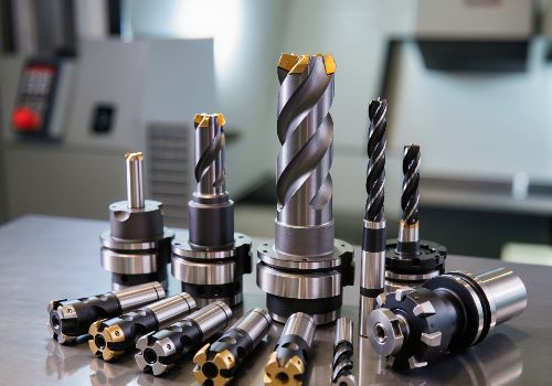
1. Optimize Tool Selection and Geometry
Choose the Right Tool Material
Match your tool substrate to your application. Tougher grades survive impact and vibration better; wear-resistant grades handle abrasion but may be more brittle. For steel with scaled surfaces, prioritize notch resistance. For high-speed continuous cutting, prioritize heat resistance.
Consider Coatings Strategically
Coatings like TiN, AlTiN, and TiAlN reduce friction and heat flow while protecting against chemical interaction. When adhesion dominates, a low-friction top layer dramatically reduces BUE. When crater wear dominates, prioritize coating stack hot hardness.
Edge Preparation Matters
Edge preparation controls impact survival. A very sharp edge cuts smoothly but chips fast under vibration. A supported edge (hone or chamfer) resists chipping but may increase cutting forces. The right edge preparation depends on your specific operation and material.
Chipbreaker Engineering
Chipbreakers manage contact length and pressure distribution, directly affecting cutting forces and heat concentration. Selecting the correct geometry for your operation (roughing with interruptions versus finishing with light DOC) often delivers more improvement than switching brands.
2. Optimize Cutting Parameters
Get Feeds and Speeds Right
Improper feeds and speeds are a primary cause of tool breakage. Beginners often run too slow, creating rubbing rather than cutting. Rubbing generates excessive heat and accelerates wear. Use a reliable feeds and speeds calculator and avoid “padlocking” too many variables that prevent optimization.
Manage Cutting Speed Carefully
Cutting speed has a much larger impact on tool life than feed rate. Increasing cutting speed causes approximately twice as much wear as increasing feed rate by the same percentage. For tools prone to crater wear or thermal issues, reducing cutting speed is often the most effective adjustment.
Control Chip Load
Chip load—the thickness of material each flute removes—must be adequate to cut cleanly without rubbing, yet not so high as to overload the tool. The “sweet spot” balances these competing requirements.
Depth of Cut Strategy
While depth of cut affects wear, its impact is less than speed or feed. Importantly, increased depth spreads wear over a longer cutting edge length—the principle behind High Efficiency Milling. For roughing, consider HEM toolpaths that maintain optimal chip load while distributing wear.

3. Ensure Rigidity and Stability
Minimize Tool Overhang
Tool deflection increases dramatically with overhang. Use the shortest possible tool length for your operation. Every millimeter of unnecessary overhang multiplies deflection risk.
Secure Workholding
Workpiece movement or vibration transmits directly to the tool. Ensure vises, fixtures, and clamps provide maximum support. For thin-walled parts, consider custom soft jaws or additional support to prevent deflection.
Address Chatter and Vibration
Chatter deteriorates surface quality and reduces tool life. Solutions include:
-
Using tools with variable flute geometries that disrupt harmonic vibration
-
Adjusting spindle speed to move out of resonant frequency
-
Ensuring balanced tool assemblies
-
Improving machine and workpiece rigidity
4. Master Toolholding and Maintenance
The Six Critical Components
Toolholding systems have six interconnected links, each requiring attention:
-
Internal collet clamping surfaces: Resin buildup causes inconsistent grip. Clean thoroughly and regularly.
-
Internal spindle and collet taper: Accumulates resin affecting concentricity. Clean at each tool change.
-
External collet and tool holder taper: Inspect and clean deposits regularly with brass brushes.
-
Clamping nut surfaces: Keep clean and burr-free. Contamination can ruin new collets.
-
Thrust bearings: Maintain smooth operation; rough movement indicates contamination.
-
Tool holders: “Fretting” or “bronzing” causes inconsistent gripping and potential spindle failure if ignored.
Replace Collets Regularly
Collets should be replaced approximately every 400-600 runtime hours. Heat cycles remove tempering, reducing elasticity. Instead of over-tightening worn collets (which creates eccentricities), replace them—the cost of a new collet often equals one shift’s worth of broken tools.
Measure and Manage Runout
Runout changes chip load and forces flutes to work unevenly. Even 5-10% runout as a percentage of chip load significantly impacts tool life. Measure runout for all toolholders, discard egregious ones, and clean meticulously. Consider “clocking” toolholders to minimize combined spindle/toolholder runout.
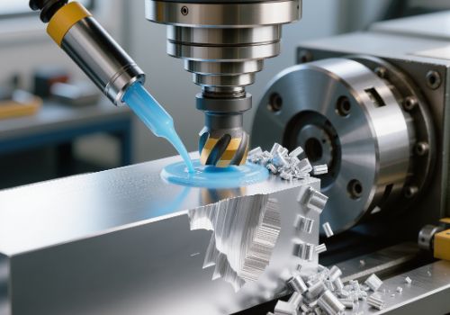
5. Master Lubrication and Chip Management
Use Appropriate Lubrication
Certain materials require lubrication without exception. Aluminum, for example, has a chemical affinity to cutter materials and will weld itself to the tool without proper lubrication. A mister system works well for machines without enclosures. Even periodic manual application of WD40 can work, though misters provide consistency.
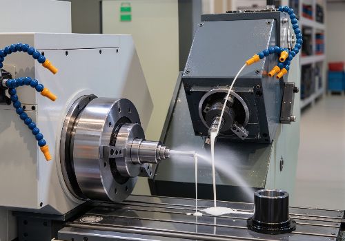
Be Paranoid About Chip Clearing
Chips are not harmless—they can work-harden, recut, and damage cutters. Chips carry away heat from the cut; removing them helps control temperature. They can also get caught between cutter and workpiece, damaging both surface finish and tool.
Effective chip clearing requires:
-
Flood coolant or strong mist/air properly aimed
-
Adequate pressure, volume, and nozzle positioning
-
Consideration of multiple nozzles for complex cuts
6. Apply Advanced Strategies
High Efficiency Milling (HEM)
HEM toolpaths use lower radial engagement and higher axial depth to spread wear over the entire cutting edge length. This prevents localized wear and prolongs tool life while maintaining material removal rates.
Tool Life Monitoring
Modern CNC machines can track tool runtime via system variables, triggering replacement when thresholds reached. Digital probes can check wear, breakage, and chipping. Spindle load monitoring provides early warning—increased cutting forces signal developing wear.
Optimize Chip Formation
Tool life improves with proper chip formation. Select appropriate feed rate, speed, and rake angle. Use sharp cutting edges, coolant, and effective chip breakers. When chips shift from consistent curls to long stringers, probability of recutting and impact rises.
Material-Specific Strategies
-
Steel: Notch wear on scaled surfaces; crater wear at higher speeds
-
Stainless steel: Work hardening and adhesion dominate; prioritize stable coolant and sufficient feed to cut under hardened layer
-
Aluminum: Use fewer flutes (2-3) for chip evacuation; never use 4-flute cutters for pocketing as chips bind and jam

Practical Implementation Checklist
Daily/Per Setup
-
Inspect tool condition under magnification
-
Verify tool overhang is minimized
-
Check workholding security
-
Ensure coolant nozzles properly aimed
-
Clear chips from work area
Weekly
-
Clean collets and toolholders thoroughly
-
Measure runout on critical tool assemblies
-
Inspect toolholder tapers for damage or buildup
-
Verify chip conveyor/auger operation
Monthly
-
Replace collets if approaching 400-600 hour threshold
-
Analyze tool life data for patterns
-
Review spindle load monitoring trends
-
Update feeds and speeds based on actual performance
Conclusion: Prevention Through System Approach
Preventing tool breakage in CNC machining is not about finding a single magic bullet—it requires a systematic approach addressing all aspects of the machining process. By understanding failure modes, optimizing tool selection and parameters, ensuring rigidity, maintaining equipment, and implementing proactive monitoring, you can dramatically reduce breakage incidents.
The most successful shops view tool breakage prevention as an ongoing process of observation, analysis, and continuous improvement. Each broken tool carries a lesson—a signal about some aspect of the process that needs attention. By learning to read these signals and respond systematically, you can achieve longer tool life, better part quality, and higher profitability.
Ready to optimize your tool life? Start by auditing your current tooling practices against this guide. Identify one area for improvement—perhaps collet maintenance, parameter optimization, or chip management—and implement changes systematically. Your tools—and your bottom line—will thank you.