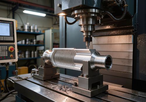
Reducing vibration in CNC machining requires a systematic approach that addresses the four pillars of stability: machine rigidity, tooling selection, cutting parameters, and workholding. By understanding the root causes of regenerative chatter and implementing proven countermeasures—from optimizing spindle speed and tool geometry to using advanced damping technologies—machinists can eliminate the “screaming” that destroys surface finishes, shortens tool life, and compromises part quality.
Introduction: The High Cost of Vibration
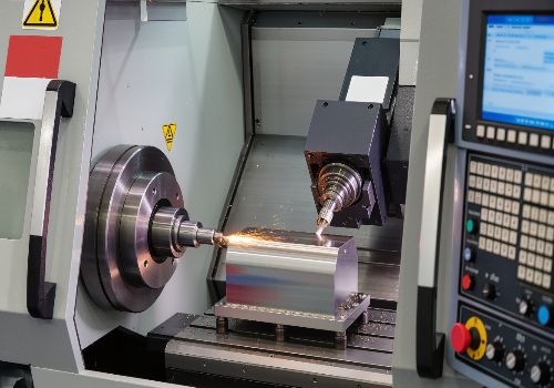
In the world of CNC machining, vibration is more than an annoyance—it’s a productivity killer. The distinctive squeal or chatter that signals instability in the cut is the sound of profit being eroded. The costs are substantial: surface finish degradation that turns precision parts into scrap, accelerated tool wear that multiplies tooling expenses, reduced material removal rates that extend cycle times, and potential damage to spindles and machine components that lead to costly repairs.
But perhaps most frustrating, vibration is often misunderstood. Many machinists respond by reducing feeds and speeds, which frequently makes the problem worse. The reality is that vibration is a predictable physical phenomenon. By understanding its causes and implementing systematic solutions, you can achieve stable, quiet machining even in challenging applications.
This comprehensive guide will equip you with the knowledge and strategies to diagnose, prevent, and eliminate vibration across your CNC operations.
Understanding the Enemy: What Is Chatter?
Before you can defeat vibration, you must understand what you’re dealing with. Chatter is not random noise—it’s a self-excited vibration that feeds on itself through a phenomenon called regenerative chatter.
The Regenerative Cycle
Imagine a cutting tool passing over a surface it has just machined. If the previous pass left a slight waviness, the tool encounters those waves on the next pass. The varying chip thickness causes the cutting force to fluctuate, which intensifies the vibration, which in turn creates deeper waves. This cycle continues, amplifying until the tool loses contact with the workpiece or the cut becomes catastrophically unstable .
This regenerative effect is why chatter often appears suddenly and escalates rapidly. Once initiated, the vibration builds on itself exponentially.
Chatter vs. Forced Vibration
It’s important to distinguish between chatter (self-excited vibration) and forced vibration (external excitation):
| Type | Cause | Characteristics | Solution |
|---|---|---|---|
| Forced Vibration | Imbalance, misalignment, external sources | Frequency matches external source; often constant | Balance tools, align components, isolate machine |
| Regenerative Chatter | Self-excited feedback loop | Frequency near machine natural frequency; grows with cut | Adjust parameters, increase rigidity, use damping tools |
The Four Pillars of Vibration Control
1. Machine and Setup Rigidity
The foundation of stable machining is a rigid system. Every component—from the machine base to the tool holder—contributes to overall stiffness. The weakest link determines stability.
Machine Foundation:
Your CNC machine must sit on a solid foundation. A single continuous slab of reinforced concrete is required—machines straddling multiple slabs or sitting on cracked foundations will never achieve chatter-free operation . Vibration pads or leveling mounts can help isolate the machine from external vibrations but cannot compensate for an inadequate foundation.
Machine Condition:
Worn components create play that amplifies vibration:
-
Spindle bearings: Excessive runout causes uneven chip loading. Check runout at the spindle taper; aim for <0.0002″ (0.005 mm) .
-
Ball screws and linear guides: Wear introduces backlash and play. Regular maintenance and lubrication are essential.
-
Couplings and belts: Worn belts or loose couplings can introduce harmonic vibrations.
Tool Overhang: The 10% Rule:
Tool rigidity is inversely proportional to the cube of the overhang length. A 10% reduction in tool length results in approximately 25% increase in tool stiffness . The rule of thumb: keep tool stickout to no more than 3 times the tool diameter for milling operations.
For turning, the relationship is even more critical. A steel boring bar remains stable up to a stickout of 3 times diameter; carbide bars can extend to 5 times diameter . When extreme reach is unavoidable, special vibration-dampening boring bars with tuned mass absorbers are essential.
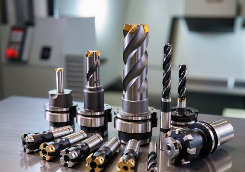
2. Tooling Selection and Geometry
Your cutting tool is the primary interface with the workpiece. Its geometry and condition directly influence stability.
Variable Geometry Tools:
Conventional tools with evenly spaced flutes create a regular pattern of tooth impacts that can build into resonance. Variable helix and unequal flute spacing tools are specifically designed to disrupt harmonic vibrations . By breaking up the regular pattern, these tools prevent the buildup of resonant energy.
The Flute Count Question:
More flutes generally provide smoother cutting because more flutes are engaged simultaneously, stabilizing the cut . However, the relationship isn’t linear. For roughing, fewer flutes with larger chip valleys can actually reduce vibration by preventing chip packing. For finishing, more flutes (5-7) often produce better results.
Cutter Diameter and Length:
Larger diameter tools are exponentially stiffer. Stiffness increases with the fourth power of diameter—a 12 mm tool is 16 times stiffer than a 6 mm tool . Use the largest diameter tool that geometry permits.
Tool Coatings and Material:
Coatings like AlTiN and TiAlN reduce friction and heat flow while protecting against chemical interaction. For aluminum, polished flutes prevent material adhesion and built-up edge formation that can trigger vibration .
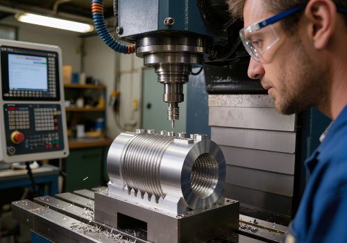
Tool Sharpness:
A dull tool doesn’t cut—it rubs. This rubbing creates friction, heat, and vibration. Implement a strict tool life management system and inspect cutting edges under magnification regularly. When flank wear (VB) reaches 0.2 mm, vibration risk increases dramatically .

3. Cutting Parameters: Finding the Stability Sweet Spot
Chatter is a resonant phenomenon, meaning certain spindle speeds will excite vibration while others will not. The key is finding stable “islands” within the sea of instability.
Spindle Speed Tuning:
The most powerful single adjustment for controlling chatter is spindle speed. Stability lobe theory reveals that there are specific RPM ranges where stable cutting is possible even at high depths of cut .
The 5-10% Rule:
If you encounter chatter:
-
Try increasing spindle speed 5-10% first —this often moves you into a stable region
-
If that doesn’t work, try decreasing by 5-10%
-
Continue making small adjustments until you find a stable “sweet spot”
This works because changing RPM shifts the frequency at which the tool teeth strike the material, potentially moving you out of a resonant condition .
Chip Load: The Goldilocks Zone:
One of the most common causes of chatter is too light a chip load. When feed per tooth is too low, the tool rubs rather than cuts. This rubbing generates heat, accelerates wear, and creates resonance that leads to chatter .
The fix: increase feed rate to achieve proper chip thickness. Many machinists instinctively slow down when they hear chatter, but sometimes speeding up the feed is the solution.
Depth of Cut Strategy:
-
Radial engagement (stepover): Lower radial engagement reduces cutting forces and vibration risk. For finishing, use 5-10% of tool diameter .
-
Axial depth: For thin walls or long tools, using full axial depth with low radial engagement (HEM/adaptive toolpaths) distributes forces along the entire cutting edge, reducing localized vibration .
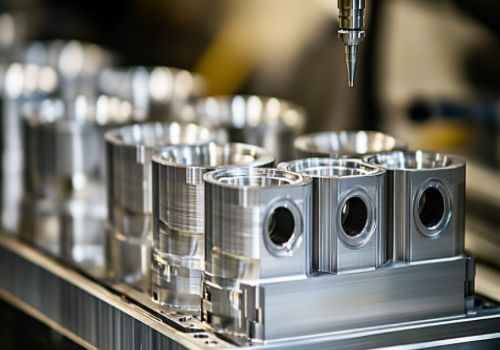
4. Workholding Rigidity
The workpiece must be as rigid as the machine. Any movement here will be amplified throughout the system.
Clamping Force:
Ensure clamping forces are adequate and evenly distributed. For thin-walled parts, use custom soft jaws that contact the entire surface rather than point loads.
Support Strategies:
-
For thin walls: Use backing plates, epoxy fixturing, or temporary supports during machining
-
For long parts in lathes: If unsupported length exceeds 3 times diameter, use a tailstock. For ratios above 10:1, consider a steady rest
-
For irregular shapes: Custom fixtures that cradle the part provide superior stability
Check for Gaps:
Before machining, verify that the workpiece is fully seated. A 0.001″ gap under a clamp can allow micro-movements that initiate chatter.
Advanced Vibration Reduction Technologies
Damping Toolholders
Modern toolholding technology offers significant vibration reduction capabilities:
-
Hydraulic chucks: Provide excellent damping through an oil-filled chamber that absorbs vibrations . Can reduce vibration by 30% compared to conventional holders .
-
Shrink-fit holders: Offer superior rigidity but less damping than hydraulic
-
Mechanical damping systems: Some toolholders incorporate tuned mass dampers specifically designed to absorb specific frequency ranges
Active Chatter Detection and Suppression
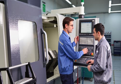
Modern CNC controls increasingly incorporate advanced vibration management:
Sensor-Based Systems:
A 2025 study in Precision Engineering describes lathe spindles equipped with displacement sensors that communicate with the CNC control to detect chatter vibrations in real-time . These systems use algorithms based on multiple samples per revolution to calculate chatter indicators. When detected, an autonomous algorithm adjusts spindle speed based on the natural frequency determined from the chatter vibration frequency .
Sensor-Less Approaches:
Researchers have developed methods using existing machine data:
-
Spindle motor current command extracted from the CNC can detect chatter without additional sensors
-
Axis encoder feedback can be analyzed to identify chatter energy and automatically manipulate spindle speed
Stability Lobe Analysis
For those wanting to take vibration control to the scientific level, Stability Lobe Diagrams plot the boundary between stable and unstable cutting conditions across different spindle speeds . These diagrams reveal “sweet spots”—specific RPM ranges where you can take significantly deeper cuts without chatter.
While determining these lobes traditionally required complex modal analysis, modern software tools can help machinists optimize cut parameters to stay within stable regions.

Material-Specific Vibration Strategies
Different materials present unique vibration challenges:
Aluminum
-
High speeds (10,000+ RPM) are effective, but tool rigidity still matters
-
Use high helix, polished flutes for excellent chip evacuation
-
Watch for chip packing—tools designed for efficient evacuation are essential
Stainless Steel
-
Work-hardens quickly, creating tougher cutting conditions
-
Requires strong geometries (lower helix, positive rake) and excellent chip control
-
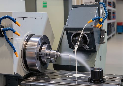
Coolant is essential—use through-coolant tools to manage heat
Titanium
-
Prone to chatter due to low thermal conductivity and elasticity
-
Use low radial engagement with high axial depth (adaptive milling is key)
-
Sharp tools degrade fast—look for edge prep and coatings that handle heat
-
Thin walls are problematic; focus on better cooling and reduced engagement
Cast Iron
-
Generally low risk for chatter, but vibration can still occur with unstable setups
-
Use rigid setups and consistent feed rates to avoid tool bounce in interrupted cuts
Inconel / Nickel Alloys
-
Tough, work-hardening, poor heat dissipation
-
Needs low stepovers, steady engagement, and coated tools
-
Run slower but maintain aggressive feed per tooth to avoid rubbing
Practical Troubleshooting Guide
When you encounter vibration, use this systematic approach:
| Symptom | Likely Cause | Adjust This |
|---|---|---|
| Loud screaming, visible waves | System resonance | Adjust spindle speed ±5-10% |
| Squealing on light cuts | Chip load too light | Increase feed or reduce RPM |
| Vibration in corners | Excessive engagement | Use smaller tool, reduce stepover, or adjust corner radius strategy |
| Chatter in deep pockets | Tool too long | Shorten stickout, use stub-length tool, reduce depth of cut |
| Random vibration, poor finish | Workpiece movement | Check clamping, tailstock support, jaw contact |
| Chatter only on finishing passes | Tool deflection | Reduce radial engagement, check runout, use sharper tool |
| Vibration increases with tool wear | Dull tool | Replace tool earlier; monitor wear patterns |
Quick Reference: Vibration Prevention Checklist
Machine Setup
-
Machine on solid, continuous concrete foundation
-
Machine level and properly maintained
-
Spindle runout ≤0.0002″ (0.005 mm) at taper
-
Ball screws and guides lubricated and adjusted
Tooling
-
Tool stickout minimized (≤3× diameter where possible)
-
Variable helix or unequal flute spacing for harmonic disruption
-
Tool sharp and appropriate for material
-
Runout measured and ≤0.0002″ at tool tip
-
Correct number of flutes for the application
-
Balanced tool assembly for high-speed operations
Workholding
-
Workpiece securely clamped with full contact
-
Tailstock used for parts exceeding 3:1 length-to-diameter ratio
-
Additional support for thin walls or delicate features
-
No gaps between workpiece and fixture
Parameters
-
Chip load adequate (not rubbing)
-
Spindle speed tuned away from resonant frequencies
-
Radial engagement appropriate (5-10% for finishing)
-
Adaptive toolpaths used for constant engagement
-
Coolant properly aimed and at correct concentration
Case Study: Eliminating Chatter in Titanium Aerospace Components
The Challenge: A manufacturer of titanium aerospace brackets was experiencing severe chatter when machining thin web sections (1.2 mm thickness). Tool life was 15 minutes per edge, surface finish exceeded 3.2 µm Ra, and scrap rates were 18%.
The Solution:
-
Tooling upgrade: Switched to variable helix end mills with unequal flute spacing
-
Toolholding: Replaced ER collet chucks with hydraulic holders (reduced runout from 0.008 mm to 0.002 mm)
-
Parameters: Reduced radial engagement from 30% to 8%; increased feed per tooth from 0.05 mm to 0.08 mm; tuned spindle speed to a stability lobe identified through testing
-
Toolpath: Implemented adaptive clearing toolpaths that maintain constant engagement
-
Coolant: Added through-spindle coolant at 1,000 PSI for better heat evacuation
The Results:
-
Tool life increased: From 15 minutes to 55 minutes per edge
-
Surface finish improved: From Ra 3.2 µm to 0.8 µm
-
Scrap reduced: From 18% to 3%
-
Cycle time decreased: By 22% due to higher material removal rates
-
Chatter eliminated: Stable, quiet machining achieved across all operations

Conclusion: A System Approach to Vibration Control
Vibration in CNC machining is not a mystery—it’s a predictable physical phenomenon with proven solutions. The key to success is taking a systematic approach that addresses all four pillars of stability:
-
Machine Rigidity: Ensure your machine, foundation, and setup are as rigid as possible
-
Tooling Selection: Use variable geometry tools, minimize overhang, and maintain sharp cutting edges
-
Cutting Parameters: Find the stability sweet spot through spindle speed tuning and proper chip loading
-
Workholding: Secure the workpiece with full contact and adequate support
By implementing these strategies, you can transform unstable, screeching cuts into smooth, quiet operations. The benefits extend beyond eliminating noise: longer tool life, better surface finishes, higher material removal rates, and increased confidence to take on challenging applications.
Remember: vibration is a signal, not a mystery. Listen to what your machine is telling you, apply these principles systematically, and you’ll achieve the stable, productive machining that separates exceptional shops from the rest.
Ready to eliminate vibration from your CNC operations? Contact our machining experts for a comprehensive vibration assessment and customized solutions for your most challenging applications.