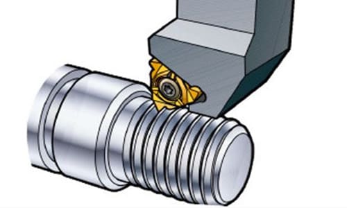
The thread is formed along a helical line on the surface of a cylindrical workpiece, with continuous protrusions and grooves of the same cross section.
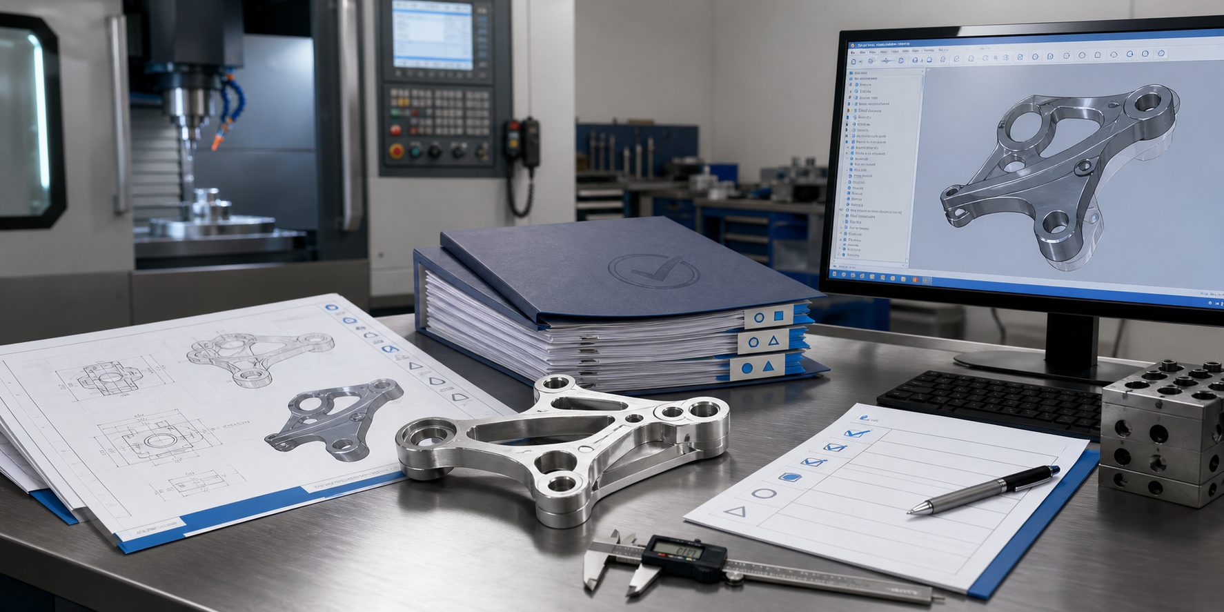
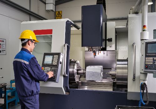
In machinery manufacturing, threaded parts are widely used. Processing threads by turning is a commonly used processing method at present. Four standard threads of metric system, inch system, modulus and diameter control can be turned on the horizontal lathe. No matter what kind of thread is turned, a strict motion relationship between the turning spindle and the tool must be maintained: that is, every time the spindle rotates, the tool should uniformly move the distance of one lead.
Their motion relationship is to ensure that: the main shaft with the workpiece rotation, the movement diameter of the main shaft is transmitted to the box; From the feed box to the lead screw after changing speed; The lead screw and the opening and closing nut on the slide box cooperate to drive the tool holder to move in a straight line, so that the rotation of the workpiece and the movement of the tool are driven by the spindle to achieve, so as to ensure the strict motion relationship between the workpiece and the tool.
In the actual thread turning, due to various reasons, there is a problem in a certain link of the movement from the spindle to the tool, which causes a fault during thread turning and affects normal production. At this time, it should be solved in time.
Common faults and solutions when turning threads are as follows:
First: Gnawing cutter
Fault analysis: The reason is that the turning tool is installed too high or too low or too long, the workpiece is not clamped firmly or the turning tool is severely worn.
Solution:
- The turning tool is installed too high or too low, and the tool rod protrudes too long: if it is too high, when the turning tool reaches a certain depth, the flank surface of the turning tool will withstand the workpiece, increasing the friction force, and even make the workpiece bend, resulting in the phenomenon of gnawing.If it is too low, the cutting is not easy to discharge, the direction of the radial force of the turning tool is the center of the workpiece, and the gap between the constant feed screw and the nut is too large, so that the depth of the cutting tool will automatically tend to deepen, so that the resistance increases and the workpiece is lifted up, causing gnawing. At this time, the height of the turning tool should be adjusted in time to strengthen the strength of the tool holder so that the tool tip is at the same height as the axis of the workpiece. In rough cutting, the position of the tool tip is about 1% D higher than the center of the workpiece (D indicates the diameter of the workpiece to be machined), which is good for chip removal. When finishing, it is slightly lower than the center of the workpiece to improve the tooth flank finish.
- The workpiece is not firmly clamped: the rigidity of the workpiece itself cannot withstand the cutting force during turning, so excessive deflection occurs, which changes the center height between the turning tool and the workpiece (the workpiece is raised), resulting in a sudden increase in the cutting depth, and gnawing appear. At this time, the workpiece should be clamped firmly, and a live center can be installed on the tailstock to increase the rigidity of the workpiece.
- Excessive wear of the turning tool: causing the cutting force to increase, bending the workpiece, and gnawing the tool. At this time, the turning tool should be sharpened.

Second: Disorderly buckle
Fault analysis: The reason is that when the lead screw rotates once, the workpiece does not rotate through an integer number of revolutions.
Solution:
- When the screw pitch of the lathe can not be fully divided by the workpiece processed: open and close the nut, shake the saddle to the starting position, so that when the nut is closed again, it will occur that the turning tool tip is not in the spiral groove of the previous tool, so that there is disorderly buckle. The solution is to use reverse turning method to return the tool, that is, at the end of the first stroke, do not lift the opening and closing nut, the knife along the radial exit, the spindle will be reversed, so that the turning tool along the longitudinal return, and then the second stroke. In this reciprocating process, because the transmission between the spindle, the lead screw and the tool holder has not been separated, the turning tool is always in the original spiral groove, there will be no disorderly buckle.
- For threads whose pitch of the lathe lead screw is divisible by the processed part: both the workpiece and the lead screw are rotating. After lifting the opening and closing nut, it is necessary to wait for the lead screw to turn around at least once before closing the opening and closing nut again. In this way, when the lead screw turns, the workpiece turns an integer times, the turning tool can enter the spiral groove of the previous knife car, there will be no disorderly buckle, can be used to open the opening and closing nut, manual knife back. This is fast, conducive to improving productivity and maintain the lead screw accuracy, at the same time, the lead screw is safer.
Third: Multi-line thread pitch
There is such a technical requirement in the technical conditions of multi-thread threads: the pitch of multi-thread threads must be equal. In order to ensure the accuracy of the pitch, when turning multi-line threads, the method of dividing the threads is mainly solved. Using the small scale to divide the thread can completely guarantee the thread dividing accuracy of the multi-thread thread, or use the chuck jaw. Use the two tops to support the two center holes, and the chicken heart chuck is mixed with the chuck jaws. After one head is processed, the other head is processed, the thimble of the tailstock is moved back, and the heart chuck head is replaced with a claw. Two ends use four claws to divide at 180 degrees; four claws process four heads at 90 degrees; three claws process three heads at 120 degrees.
Accurate line division during thread turning is the key to ensure processing quality. If there is an error in the line division of the thread, it will directly affect the pitch of the multi-thread thread. If it is a fitting, it will directly affect the matching accuracy of the internal and external threads and reduce the service life of the product. If the sub-line is seriously out of tolerance, the processed product may be a waste product. Therefore, when turning double-first threads, the branch line of the thread is in the “most important” position in the entire processing process. In a word, thread line method selection must be based on the precision of the workpiece processing quantity, machine tool equipment, cutting performance of tool materials, workpiece strength and workpiece in the process of processing may produce deformation, such as elastic deformation of the workpiece, thermal deformation and other factors for comprehensive consideration.
According to the formation principle of multi-wire thread, there are many kinds of parting methods in theory when turning multi-wire thread. The small slide scale is used to determine the amount of movement to divide the line. The processing method is left and right cutting. But sometimes the pitch diameter size is guaranteed, and the pitch accuracy cannot be guaranteed. It should be noted that when using the left and right cutting method to turn the multi-thread thread, it is absolutely not allowed to turn one spiral groove before turning another spiral groove.

The following steps shall be followed during processing:
- First remove the empty stroke of the middle and small sliding plates, and then adjust them to the zero scale. Adjust the angle of the small sliding plate to zero. Adjust the clearance properly.
- Reserve allowance for the first spiral groove of rough turning and finish turning. At this time, remember the scale values of the middle and small sliding plates during rough turning. While ensuring the surface quality of the tooth profile side, the borrowing amount of the small sliding plates should be as small as possible, generally subject to the turning out.
- The second spiral groove of rough turning is divided by small sliding plate, which moves forward or backward by one pitch. The feed of the middle sliding plate is the same as the first spiral groove of the car, and the borrowing amount of the small sliding plate is as small as possible. Use the left and right cutting method to correct the parting error as much as possible.
- The finishing turning tool shall be changed by using the circular turning method, combined with the left and right cutting methods to process the double thread. Before finishing turning, the split error shall be verified by the circular turning method. If the turning method is correct, the turning tool has no problem, but the split error is large, which means that the small sliding plate has clearance or angle deviation, which should be adjusted in time. When turning each spiral groove, the longitudinal borrowing amount and radial feed of the turning tool should be the same.
- Finish turning each spiral groove according to the above method to ensure that the pitch diameter size meets the requirements and the pitch accuracy error is within the range.