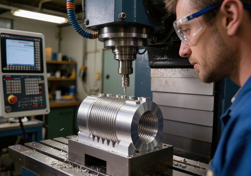
A poor surface finish on your CNC-machined part is more than just a cosmetic issue—it’s a symptom of underlying problems that can affect part functionality, tool life, and your bottom line. Achieving a smooth, consistent finish is a critical sign of a well-tuned machining process.
This comprehensive guide will help you diagnose and fix the most common causes of poor surface finish, turning frustration into flawless results.
The Root Causes: A Problem-Solving Framework
Surface finish issues typically stem from four main areas: Machine Condition, Tooling, Programming/Setup, and Material. By systematically checking each category, you can efficiently pinpoint the culprit.
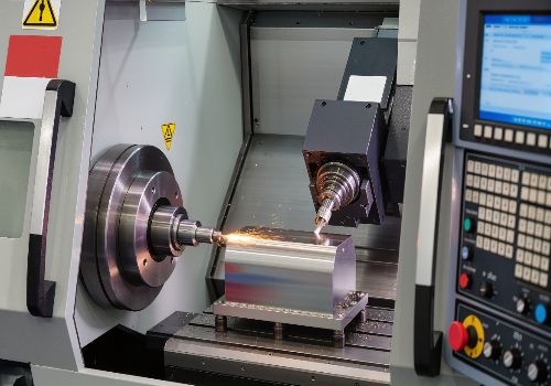
1. Machine-Related Issues: Your Foundation Must Be Solid
If your machine isn’t stable and accurate, achieving a good finish is impossible.
-
Vibration and Chatter: This is enemy number one for surface finish. Chatter creates a distinctive pattern of regular waves or lines on the part. It occurs when there’s insufficient rigidity in the system.
-
Check: Machine foundation, leveling, and mounting bolts. Ensure workholding (vises, clamps, fixtures) is extremely secure. A part that can vibrate or move will chatter.
-
Symptom: Audible squealing or ringing during the cut, with a visible “chatter pattern” on the surface.
-
-
Worn or Loose Machine Components: Backlash in ball screws, worn linear guides, or a loose spindle taper can all cause inconsistent movement, translating directly into a poor finish.
-
Check: Perform regular maintenance. Indicate your spindle taper for runout. Check axis backlash using machine diagnostics or a dial indicator.
-
-
Inadequate Spindle Power or Speed: Forcing a large tool with high feed rates on an underpowered spindle can cause it to bog down, creating tearing instead of shearing.
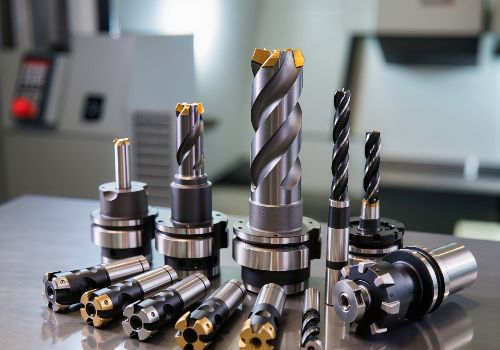
2. Tooling Problems: The Cutting Edge Makes the Cut
The tool is your direct interface with the material. Problems here are magnified on the part’s surface.
-
Dull, Worn, or Damaged Tools: A dull tool doesn’t cut—it rubs and tears the material, generating excessive heat and leaving a rough, often work-hardened surface. This is the most common cause of poor finish.
-
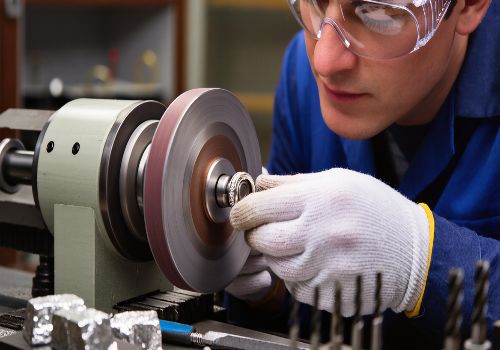
Fix: Implement a strict tool life management system. Inspect cutting edges under magnification for wear (flank wear, chipping). Don’t try to squeeze “one more part” from a worn tool.
-
-
Incorrect Tool Selection: Using the wrong tool for the job is a guaranteed path to a bad finish.
-
Geometry: A tool with too few flutes can lack stability; too many flutes can limit chip evacuation. For finishing, use tools designed specifically for that purpose, often with a larger corner radius or wiper flat.
-
Material Match: Ensure your tool substrate and coating are suitable for the workpiece material (e.g., aluminum-specific tools have highly polished flutes to prevent material adhesion).
-
-
Tool Runout: Even a few tenths of a millimeter of runout at the tool tip can cause one flute to do most of the work, leading to uneven wear, vibration, and poor finish.
-
Check: Use a dial test indicator at the tool tip. Invest in high-quality, precision tool holders like hydraulic chucks or shrink-fit holders to minimize runout.
-
-
Incorrect Tool Holder: A collet chuck that’s worn or a holder with poor grip will allow the tool to deflect or vibrate.

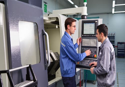
3. Programming & Process Errors: The Blueprint for Success
Your CAM program and cutting strategy dictate exactly how the tool interacts with the part.
-
Wrong Feeds and Speeds (Cutting Parameters):
-
Feed Rate Too High: Creates a coarse, heavily scalloped surface.
-
Feed Rate Too Low: Allows the tool to rub and burnish the material instead of cutting it, often creating built-up edge and a torn finish.
-
Surface Speed (RPM) Too Low: Can cause tearing in materials like aluminum.
-
Rule of Thumb: For a better finish, increase RPM and reduce feed per tooth, while maintaining an adequate chip load to avoid rubbing.
-
-
Poor Toolpath Strategy:
-
Climb vs. Conventional Milling: For most CNC applications, climb milling (where the cutter rotates with the feed direction) provides a cleaner shearing action and better finish than conventional milling.
-
Stepover Too Large: The distance between toolpasses should be reduced for finishing passes. A good rule is 5-10% of the tool diameter for a fine finish.
-
Lack of a Dedicated Finishing Pass: Trying to achieve both final dimension and final finish in one aggressive pass rarely works. Use a separate, light finishing pass (0.1-0.5mm stock removal) with optimized parameters.
-
-
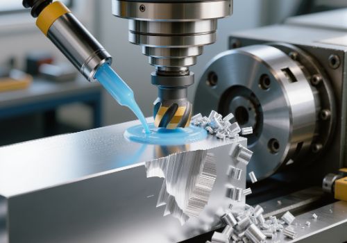
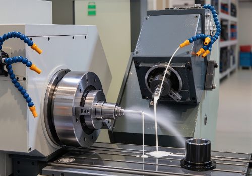
Inadequate Chip Evacuation: Recut chips are abrasive and will mar a finished surface. Use proper chip clearing techniques, especially in pockets and deep cavities (e.g., peck drilling, compressed air, or high-pressure coolant).
4. Material & Workpiece Factors
The material itself can present challenges.
-
Unstable or Thin-Walled Workpieces: Lack of rigidity in the part leads to deflection and vibration under cutting forces. Use strategic support, softer jaws, or different clamping to bolster rigidity.
-
Material Inconsistency: Variations in hardness, inclusions, or gummy materials (like certain stainless steels or soft aluminum) can cause tearing and built-up edge, requiring specific tool geometries and parameters.
Quick-Diagnosis Troubleshooting Table
| Symptom on Part | Most Likely Causes | First Things to Check |
|---|---|---|
| Regular, wavy lines (Chatter Marks) | Vibration/Lack of Rigidity | 1. Tool & Workpiece clamping 2. Spindle speed (try adjusting RPM) 3. Use shorter, more rigid tool |
| Rough, Torn, or Fuzzy Surface | Dull Tool, Wrong Parameters | 1. Tool condition under magnification 2. Increase cutting speed (RPM) 3. Check for climb vs. conventional milling |
| Burnished or Discolored Surface | Excessive Heat, Rubbing | 1. Feed rate is too low 2. Tool is dull 3. Use coolant/air blast effectively |
| Varied Finish (good in some areas, bad in others) | Tool Deflection, Poor Toolpaths | 1. Tool length/rigidity 2. Stepover value in finish pass 3. Chip recutting in corners |

Advanced Fix: Addressing Chatter and Vibration
Since chatter is so common and destructive, it deserves a deeper look. Here is a systematic approach to eliminating it:
-
Increase Rigidity: Shorten the tool overhang, use a larger diameter tool, and ensure the workpiece is clamped directly over support.
-
Adjust Cutting Parameters: Change the spindle speed. Often, a small adjustment (5-15% up or down) moves you out of a resonant frequency causing chatter. Reduce radial depth of cut.
-
Use Anti-Vibration Tooling: Consider tools with variable helix/pitch angles or damping technology designed to break up harmonic vibration.
The Finishing Pass Checklist
For a guaranteed improvement, follow this checklist for your final finishing operation:
-
Tool: Fresh, sharp tool designed for finishing. Check for minimal runout.
-
Holder: Clean, precision holder (shrink-fit or hydraulic preferred).
-
Parameters: Higher RPM, reduced feed per tooth, light axial depth of cut (0.1-0.5mm).
-
Stepover: Small radial stepover (5-10% of tool diameter).
-
Strategy: Climb milling, with a dedicated toolpath for finishing.
-
Chips: Ensure chips are being cleared away from the cutting zone.
-
Machine: Confirm the machine is properly maintained and warmed up.

Conclusion: A Methodical Path to Perfection
A poor surface finish is a message from your process. By listening to it and investigating systematically—starting with tool condition, workholding rigidity, and basic cutting parameters—you can consistently diagnose and solve the problem. Remember, achieving a mirror-like finish is rarely about one magical setting; it’s about the meticulous control of all the variables in your machining ecosystem.
Invest the time to understand these principles, and you’ll not only fix poor finishes but also gain deeper control over your entire CNC process, leading to higher quality, efficiency, and reliability.