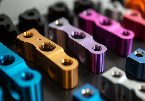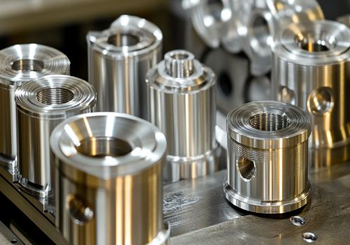
Improving surface finish in CNC machining requires a systematic approach that combines optimized cutting parameters, proper tool selection, rigid machine setup, and appropriate post-processing techniques. By understanding the relationship between these factors and how they interact, machinists can achieve surface roughness values below 0.4 µm Ra—the threshold for high-performance applications in aerospace, medical, and automotive industries.
Introduction: Why Surface Finish Matters Beyond Aesthetics
Surface finish in CNC machining is far more than a cosmetic concern. For components that experience cyclic loading, sliding contact, or sealing requirements, the quality of the machined surface often determines whether a part lasts for years or fails catastrophically in weeks . Roughness peaks act as stress concentrators that initiate fatigue cracks, while deep feed marks and subsurface damage accelerate wear rates dramatically.
The numbers tell a compelling story: a machined surface with Ra = 3.2 µm can reduce the fatigue limit of high-strength steel by 25-30% compared to a polished reference . In hydraulic systems, improving surface finish from Ra 2.5 µm to 0.8 µm extends seal life from 8,000 to 24,000 hours—a threefold improvement .
Different industries impose specific surface finish requirements based on functional demands :
| Industry | Typical Ra Requirement | Critical Applications |
|---|---|---|
| Medical Devices | ≤ 0.4 µm | Surgical blades, orthopedic implants |
| Automotive Engines | 0.8-1.6 µm | Crankshafts, cylinder bores |
| Optical Components | ≤ 0.1 µm | Laser mirrors, lens mounts |
| General Machinery | 3.2-6.3 µm | Gearbox housings, structural parts |
Understanding how to consistently achieve these finish requirements is essential for any serious machining operation.
The Core Factors That Control Surface Finish
Surface finish in CNC machining is influenced by five primary factors that interact in complex ways . Mastering each one is the key to predictable, repeatable results.
1. Cutting Parameters: The Primary Levers
Feed Rate: The Dominant Factor
Research consistently shows that feed rate has the greatest influence on surface roughness across materials ranging from aluminum to nickel-based superalloys . In milling, feed per tooth is the single biggest lever for controlling finish .
The relationship is dramatic: halving feed from 0.15 mm/tooth to 0.075 mm/tooth in a 12 mm four-flute end mill drops theoretical Ra from about 2.8 µm to 0.7 µm . Real-world tests on 4140 crankshafts showed that this change alone raised rotating-bending fatigue limit from 520 MPa to 680 MPa .
For turning operations, feed rate similarly dominates. Optimization studies on Inconel-718 using Response Surface Methodology (RSM) revealed that feed rate had a more significant influence on surface roughness than cutting speed, with optimal parameters of 20.0 m/min cutting speed and 0.030 mm/rev feed rate achieving Ra = 0.441 µm .
A practical formula for estimating required feed based on desired Ra is :
f = (Ra × r) / (8 × Re)
Where:
-
f = feed per revolution (mm/rev)
-
Ra = target surface roughness (µm)
-
r = tool nose radius (mm)
-
Re = cutting edge radius (mm)
Spindle Speed: The Thermal Factor
Higher spindle speeds generally improve finish by reducing built-up edge and vibration amplitude, provided chip load remains stable . In aluminum 6061 face milling, raising surface speed from 300 m/min to 600 m/min routinely cuts Ra in half .
For hardened materials, the effect is equally pronounced. In AISI 4340 at 55 HRC, speeds around 140-180 m/min with CBN inserts produce Ra below 0.6 µm and avoid the white-layer formation that kills fatigue performance .
However, speed increases must be balanced against tool wear and machine dynamics. Excessive speeds can induce chatter or accelerate thermal degradation of the cutting edge.
Depth of Cut: The Stability Factor
Shallow depths (0.2-0.5 mm) reduce cutting forces and tool deflection, directly minimizing chatter marks and waviness . In thin-wall aerospace brackets machined from Ti-6Al-4V, limiting axial depth to 0.3 mm while using high-speed trochoidal paths improved Ra from 2.4 µm to 0.9 µm and increased low-cycle fatigue life by 35% .
For finish passes, a common strategy is to use depths of 0.1-0.25 mm with optimized parameters to achieve the best possible surface .

2. Tool Selection and Geometry
Nose Radius and Edge Preparation
Larger nose radius smooths the surface but increases radial forces . A common compromise in finish passes is to use inserts with 0.8-1.2 mm radius for steels and 0.4 mm radius for aluminum .
For finishing, wiper inserts deserve special mention. These specialized tools feature a flat geometry that effectively “wipes” the surface clean, producing finishes comparable to grinding at much higher feed rates .
Edge preparation matters enormously for finish. A very sharp edge cuts smoothly but chips fast under vibration. A supported edge (hone or chamfer) resists chipping but may increase cutting forces . Tools with positive rake angles (γ = 15°) can reduce cutting forces and improve surface roughness by approximately 20% .
Tool Coatings and Flute Design
Coatings like TiAlN and AlTiN reduce friction and heat flow while protecting against chemical interaction. For aluminum, polished flutes prevent material adhesion and built-up edge formation .
Variable helix and unequal flute spacing tools are specifically designed to disrupt harmonic vibrations that cause chatter marks . These tools break up the regular pattern of tooth impacts that can build into resonance.
Tool Wear Monitoring
Tool wear directly degrades surface finish. When flank wear (VB) reaches 0.2 mm, Ra values can increase by 50% . Implement a strict tool life management system and inspect cutting edges under magnification regularly.
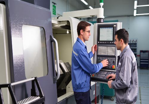
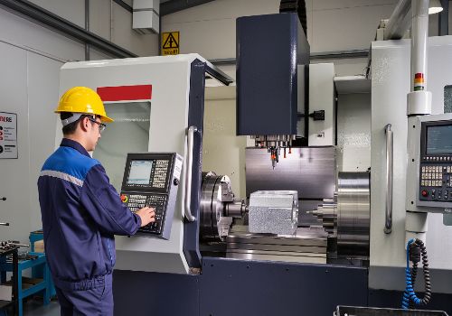
3. Machine Rigidity and Vibration Control
Chatter is enemy number one for surface finish. It creates distinctive wavy patterns that ruin both appearance and function. Multiple factors contribute to vibration :
-
Spindle radial runout should be ≤ 0.002 mm to avoid finish variations of ±0.2 µm
-
Tool overhang must be minimized—every millimeter of unnecessary length multiplies deflection risk
-
Workholding must be absolutely secure, with full jaw contact and proper clamping force
-
Machine foundation requires a single continuous slab of reinforced concrete
Advanced solutions include damping toolholders (such as hydraulic chucks) that can reduce vibration by 30% .
4. Cooling and Lubrication
Proper cooling is critical for surface finish, particularly in materials prone to work hardening or built-up edge.
Minimum Quantity Lubrication (MQL) has shown impressive results. Compared to traditional flood cooling, MQL can reduce Ra by 15% while cutting fluid usage by 80% .
For challenging materials like titanium, cryogenic cooling with liquid nitrogen can maintain Ra stable at 0.6 µm while improving surface hardness by 20% .
5. Material Characteristics
The workpiece material itself imposes limitations. Aluminum 6061 responds differently than Inconel 718, which behaves differently than hardened steel .
Heat treatment significantly affects machinability. Unaged 6061 aluminum may produce Ra = 1.2 µm, while aged material under identical parameters achieves Ra = 0.8 µm .

Advanced Strategies for Superior Finishes
High-Speed Finishing
For demanding applications, high-speed finishing with aggressive parameters can achieve exceptional results :
-
Spindle speed ≥ 10,000 RPM
-
Feed rate = 800 mm/min
-
Depth of cut = 0.1 mm
This combination can achieve Ra ≤ 0.4 µm while improving efficiency by 25% .
Toolpath Optimization
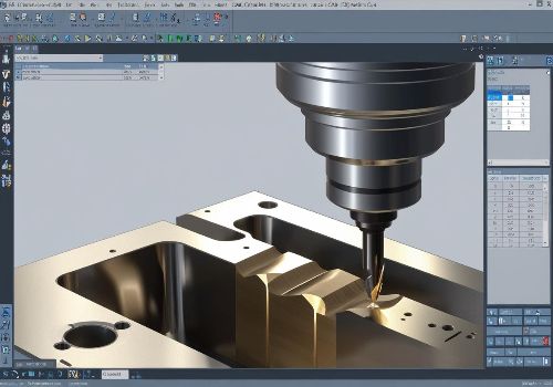
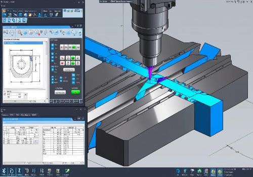
Modern CAM software offers powerful strategies for finish improvement :
Constant scallop height machining automatically adjusts stepover based on surface curvature, ensuring Ra variation stays within ±0.1 µm .
Trochoidal and adaptive toolpaths maintain constant tool engagement, eliminating force spikes that create vibration and poor finish .
Spiral finishing for holes and cavities eliminates entry/exit marks by maintaining continuous cutting motion .
In-Process Monitoring
Real-time surface measurement with white light interferometry can feed data back to the CNC control, automatically adjusting tool offsets to maintain Ra within ±0.05 µm .
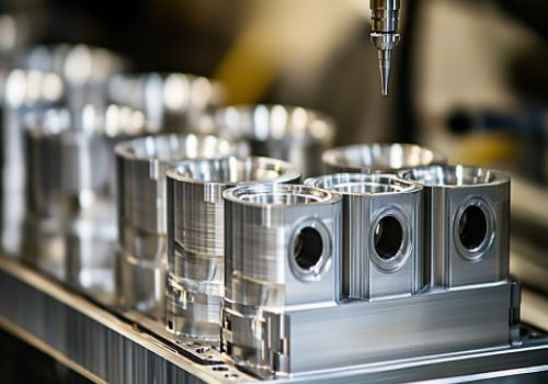
Post-Processing Techniques for Surface Enhancement
When machining alone cannot achieve the required finish, post-processing provides the final refinement. Surface treatments generally fall into three categories: mechanical, chemical, and thermal .
Mechanical Finishing Methods
Grinding produces parts with tight tolerances and fine surface finishes using rotating abrasive wheels . Silicon carbide wheels are ideal for low-tensile materials, while aluminum oxide wheels suit higher tensile strengths . Factors affecting ground finish include wheel grit size (finer grains produce smoother surfaces), wheel hardness, and vibration control .
Polishing and Buffing remove small defects and scratches. Hand polishing with diamond abrasives can reduce Ra from 1.6 µm to 0.1 µm . Buffing uses very fine abrasives on soft wheels rotating at high speeds to achieve mirror finishes .
Bead Blasting propels tiny glass or ceramic beads at high pressure to create uniform matte or satin finishes while hiding tool marks . It’s particularly effective as a pre-treatment for painting or anodizing . However, it may crack brittle plastics .
Tumbling/Barrel Finishing rotates parts with abrasive media in a barrel, providing efficient deburring and edge smoothing for high-volume production .
Lapping and Honing achieve exceptional dimensional accuracy and surface finish. Lapping uses abrasive slurry between the workpiece and a soft lap tool . Honing uses abrasive stones for finishing cylindrical surfaces, common in automotive cylinder applications achieving Ra 0.4-0.8 µm .
Chemical and Electrochemical Methods
Anodizing is an electrochemical process that creates a protective oxide layer on aluminum . Type II anodizing provides corrosion resistance and accepts dyes for color. Type III (hard coat anodizing) produces a thicker, harder layer (25-100 µm) for high-wear applications . The process involves immersing aluminum in sulfuric acid electrolyte and passing electric current, forming aluminum oxide that resists corrosion .
Electropolishing reverses the electroplating process, removing material to level micro-peaks and valleys . It’s excellent for deburring and reducing average roughness while creating a shiny, corrosion-resistant surface .
Passivation treats stainless steel by immersing it in acid (typically nitric) to dissolve free iron and strengthen the natural chromium oxide layer, dramatically improving corrosion resistance .
Chemical Oxidation creates protective oxide layers on various metals, sometimes providing decorative black finishes .
Thermal and Coating Methods
Powder Coating applies electrostatically charged dry powder (thermoplastic or thermoset polymer) that is cured under heat . The result is a tough, uniform finish that can add slight dimensions to the part .
Vapor Polishing exposes thermoplastics to chemical vapors that slightly melt the surface, achieving glass-like clarity and smoothness .
Electroless Nickel Plating deposits an even layer of nickel-phosphorus alloy without electricity, providing uniform coverage regardless of part geometry .

Selecting the Right Finish for Your Application
Choosing the appropriate finish requires balancing multiple factors :
| Factor | Considerations |
|---|---|
| Material Compatibility | Some finishes damage certain materials (e.g., bead blasting can crack thin plastics) |
| Functional Requirements | Corrosion resistance (anodizing), wear resistance (hard coating), or aesthetics (polishing) |
| Dimensional Effects | Powder coating adds thickness; tumbling may slightly alter dimensions |
| Cost & Scalability | Electroplating suits high volume; wet sanding works for hobbyists |
For functional parts requiring tight tolerances and specific surface properties, consult with your machining partner early in the design process. Companies specializing in precision finishing maintain extensive process databases—one manufacturer reports accumulating over 100,000 sets of cutting parameters to rapidly match optimal surface quality solutions .
Conclusion: A Systematic Path to Perfect Surfaces
Improving surface finish in CNC machining is not about finding a single magic setting—it requires a systematic approach addressing all aspects of the machining process .
Start by measuring current roughness on representative parts using proper equipment. Then adjust one variable at a time—typically feed rate first—while monitoring tool wear and cycle time. Small, deliberate changes often yield large returns in component durability and overall cost of ownership .
The goal is not the lowest possible Ra at any cost, but finding the sweet spot where spindle speed, feed rate, depth of cut, tool selection, toolpath strategy, and post-processing work together within acceptable cycle times . Experience confirms that reductions in roughness from 3-4 µm to below 1 µm routinely deliver 25-50% gains in fatigue strength and similar reductions in wear rate across steels, titanium, and nickel alloys .
Whether you’re machining aerospace titanium, medical-grade stainless, or automotive aluminum, the principles remain the same: understand your process, control your variables, and verify your results. The next time a finish-related failure occurs, look first at the surface that came off the machine—the fix is frequently hiding in the parameter list .
Need help achieving flawless surface finishes on your critical components? Contact our engineering team today for a free consultation on optimizing your machining process for superior surface quality.