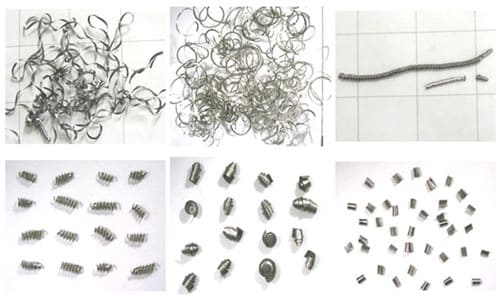
In metal cutting, some chips are rolled into a spiral shape, and they break off by themselves when they reach a certain length; some chips are broken into a C shape, a figure 6 shape; some are coil-shaped chips; some are broken into needles or small pieces , splashing around, affecting safety; some ribbon chips are wrapped around the tool and the workpiece, which is easy to cause accidents. Poor chip evacuation will affect the normal production.

1. What are the factors that affect chips?
A. Workpiece material
The alloying elements, hardness and heat treatment state of the workpiece material affect the chip thickness and chip curl. Mild steel has a larger chip thickness than hard steel; hard steel is less likely to curl than mild steel; the thickness of the chip that is not easy to curl is thinner; but when the thickness of the mild steel chip is too large, it is not easy to curl. At the same time, the shape of the workpiece is also an important factor.
B. The geometric parameters of the tool cutting area
Reasonable tool cutting area geometry parameters is the most common method to improve the controllability of chip formation and the reliability of chip breaking.
The rake angle is inversely proportional to the chip thickness, and has the best value for different materials to be processed; the entering angle directly affects the thickness and width of the chip, and the large entering angle is easy to break the chip; the radius of the tool nose arc is related to the thickness and width of the chip and the chip flow direction, small arc radius is suitable for finishing, and large radius is suitable for roughing.
The width of the chipbreaker is selected in proportion to the feedrate, the narrower chipbreaker is selected for the small feedrate, and the wider chipbreaker is selected for the large feedrate; the selection of the chipbreaker depth is inversely proportional to the feedrate, and deeper chipbreaker is selected for the small feedrate, and shallower chipbreaker is selected for large feedrate.
C. Cutting amount
The three elements of cutting amount will limit the range of chip breaking. The most important influence on chip breaking is the feedrate and back cut rate, while the cutting speed has the least effect on chip breaking within the conventional cutting speed. The feedrate is proportional to the chip thickness; the back cut rate is proportional to the chip width; the cutting speed is inversely proportional to the cutting thickness, increasing the cutting speed will narrow the effective chip breaking range.
D. Machine tools
Modern CNC machine tools use the NC editing function to periodically change the feedrate to achieve the purpose of forced chip breaking, which is usually called “programmed chip breaking”. This method has high chip breaking reliability, but low cutting economy. It is often used in processes that are difficult to break by other methods, such as deep grooves on the end face, etc.
E. Cooling and lubrication state
With the addition of cutting fluid, the effective chip breaking range becomes wider, especially when the chip breaking is easy to curl at a small feed. Using the high pressure of the cutting fluid to break chips and remove chips is an effective method in some machining methods. For example, in deep hole machining, the high pressure cutting fluid can discharge the chips out of the cutting area.
2. Formation process of chips shape
The formation process of ribbon chips can be divided into three stages:
- Basic deformation stage: the deformation caused by the chips in the process that the metal of the cutting layer and the cutting edge of the tool come into contact with the chips and break away from the workpiece material;
- Crimping deformation stage: upward curling, lateral curling, conical curling with both A and B directions;
- Additional deformation and fracture stages.

3. What’s the classification of chips
Due to the different workpiece materials, the cutting conditions are different. The shapes of chips generated during cutting are varied. The shape of the chips is mainly divided into four types: ribbon, nodular, granular and broken, as shown in the figure.


A. Ribbon Chips
This is the most common type of chipping. Its inner surface is smooth and its outer surface is furry. When machining plastic metals, such chips are often formed under the conditions of small cutting thickness, high cutting speed and large tool rake angle. Its cutting process is balanced, the cutting force fluctuation is small, and the machined surface roughness is small.
B. Nodular chips
Also known as squeezing chips. Its outer surface is serrated, and its inner surface is sometimes cracked. Such chips are often generated at lower cutting speeds, larger thicknesses, and smaller tool rake angles.
C. Granular chips
Also known as unit chips. In the process of chip formation, if the shear stress on the shear plane exceeds the fracture strength of the material, the crack spreads to the entire surface, and the chip unit falls off the material to be cut to form granular chips. As shown in Figure c.
The above three chips are only possible when machining plastic materials. Among them, the cutting process of the ribbon chip is the smoothest, and the cutting force of the unit chip fluctuates the most. Ribbon chips are the most common in production, and unit chips are rare. If the conditions of chip extrusion are changed, such as further reducing the rake angle of the tool, reducing the cutting speed, or increasing the cutting thickness, unit chips can be obtained. Conversely, ribbon chips can be obtained. This shows that the shape of the chip can be transformed with the cutting conditions. By mastering its changing law, the deformation, shape and size of chips can be controlled to achieve the purpose of chip crimping and chip breaking.
D. Brokenchips
These are chips that are brittle materials. The shape of this chip is irregular, and the machined surface is uneven. From the point of view of the cutting process, the chip deformation is very small before breaking, and the chip formation mechanism is also different from that of plastic materials. Its brittle fracture is mainly due to the stress on the material exceeding its tensile limit. Machining brittle and hard materials, such as high silicon cast iron, white iron, etc., especially when the cutting thickness is large, such chips are often obtained. Because its cutting process is very unstable, it is easy to damage the cutting tool and machine tool, and the machined surface is rough, so it should be avoided in production. The method is to reduce the cutting thickness so that the chips are needle-shaped or flake-shaped; at the same time, the cutting speed is appropriately increased to increase the plasticity of the workpiece material.
The above are four typical chips, but the shapes of the chips obtained at the processing site are various. In modern machining, cutting speeds and metal removal rates have reached very high levels, and cutting conditions are harsh, often producing large amounts of “unacceptable” chips.
Appropriate measures should be taken to control the curling, outflow and breaking of chips during the cutting process, so that an “acceptable” good chip shape is formed. The most widely used chip control method in actual machining is to grind a chip breaker on the rake face or use a compact chip breaker.