Machining thin-walled parts without warping requires a comprehensive strategy that addresses the three primary causes of distortion: residual stress from material processing, heat-induced expansion during cutting, and mechanical deflection from cutting forces. By combining stress-relieved materials, strategic workholding, optimized toolpaths, and controlled cutting parameters, machinists can successfully produce thin-walled components with wall thicknesses below 1 mm while maintaining dimensional accuracy and surface integrity.
Introduction: The Challenge of Thin Walls
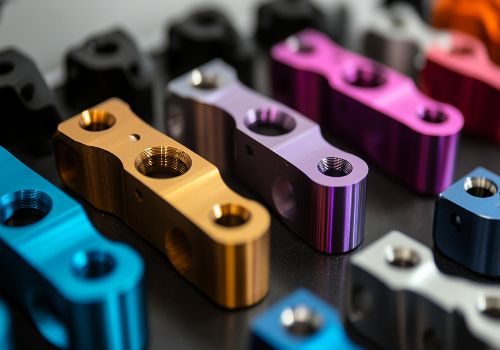
Few CNC machining challenges test a machinist’s skill like thin-walled parts. Whether it’s aerospace components requiring weight reduction, medical implants demanding biocompatible contours, or electronic housings needing minimal material, thin walls push every aspect of the machining process to its limit.
The physics is unforgiving: a wall just 0.5 mm thick has less than one-tenth the stiffness of a 2 mm wall. Cutting forces that would barely register on a solid block become catastrophic on thin sections. Heat that dissipates harmlessly in thick material causes rapid expansion and distortion in thin walls. And residual stresses locked inside the raw material, previously balanced by surrounding mass, suddenly release when material is removed, twisting and bending the part unpredictably .
Understanding these forces and implementing proven countermeasures separates successful thin-wall machining from frustrating scrap.
Understanding the Three Enemies of Thin Walls
1. Residual Stress: The Hidden Threat
Residual stress is stress that remains in a material after its original cause has been removed. Every material—rolled sheet, extruded bar, forged billet—contains locked-in stresses from its manufacturing process. When you machine away material, you upset the delicate balance these stresses maintained. The remaining material moves to find a new equilibrium, causing warpage, twisting, and dimensional changes .
The Impact: A seemingly flat aluminum plate can bow 0.5 mm or more after roughing one side. Thin ribs can curl like potato chips. Features that measured perfectly on the raw stock shift unpredictably after machining.
2. Thermal Expansion: The Invisible Force
Heat is the silent enemy of thin-wall machining. Every cut generates heat—at the tool-chip interface, through friction, and through plastic deformation of the material. In thick sections, this heat dissipates through the mass of the workpiece. In thin walls, there’s nowhere for the heat to go.
The Impact: A 100 mm aluminum wall heated by just 20°C expands by 0.045 mm—enough to throw off precision tolerances. Uneven heating creates differential expansion, warping walls that were perfectly straight when cold. When the part cools after machining, dimensions shift again, sometimes by significant margins .
3. Mechanical Deflection: The Rigidity Gap
Thin walls lack the stiffness to resist cutting forces. Even light cuts can deflect a thin wall, causing the tool to “push” the material rather than cut it cleanly. This deflection creates several problems: dimensional inaccuracy (the wall springs back thinner than intended), poor surface finish (chatter and vibration), and accelerated tool wear (the tool rubs rather than cuts) .
The Impact: A 1 mm thick aluminum wall deflects approximately 0.05 mm under a 10 N cutting force—a force easily generated by a small end mill. Multiply this by multiple passes, and accumulated error becomes significant.

Stage 1: Material Selection and Preparation
Choose the Right Starting Form
The raw material form significantly influences residual stress:
-
Cast tooling plate (e.g., MIC-6, Alca 5) for aluminum: Specifically processed to minimize internal stress. These materials are stress-relieved during manufacturing and remain dimensionally stable during machining. For thin aluminum parts, start with cast plate rather than rolled bar .
-
Stress-relieved bar stock for steels: Many steel suppliers offer stress-relieved options. Specify this for critical thin-wall components. The additional cost is often less than the scrap saved.
-
Forgings for complex shapes: For production quantities, consider starting with a forging. Forging aligns grain structure and, when properly stress-relieved, provides excellent dimensional stability .
Pre-Machining Stress Relief
For critical applications, incorporate stress relief before final machining:
Heat Treatment:
-
Aluminum: Solution heat treat and artificially age before machining. For 6061, this means T6 temper. For 7075, T7351 offers improved stress relief .
-
Steel: Normalize or anneal before rough machining. Stress relieve after roughing and before finishing.
Cryogenic Processing:
Some shops use cryogenic treatment (cooling to -300°F/-185°C) to stabilize aluminum and steel. The process relieves residual stress and can improve dimensional stability by 30-50% .
Thermal Cycling:
For ultra-precision work, thermal cycle the material—heat to 150-200°C, hold for several hours, cool slowly. Repeat two or three times. This “exercises” the material, allowing stresses to equalize.
Stage 2: Strategic Roughing
The Roughing Philosophy
Roughing thin-walled parts requires a different mindset than roughing solid blocks. The goal isn’t maximum material removal—it’s balanced material removal that maintains stress equilibrium throughout the process.
Symmetrical Roughing
Remove material evenly from both sides whenever possible. If you rough one side completely before touching the other, stresses will distort the part before finishing.
Best Practice: Flip the part multiple times during roughing, removing equal amounts from each side. For prismatic parts, rough both sides in alternating passes, maintaining the part’s stress balance .
Adaptive Toolpaths for Consistent Engagement
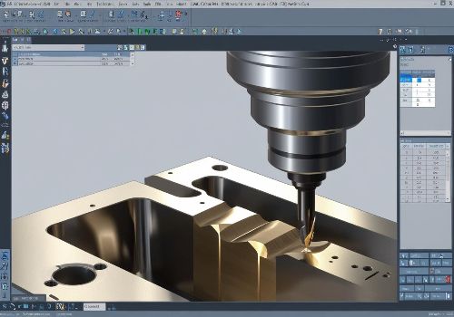
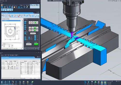
Modern CAM software offers adaptive or high-efficiency machining (HEM) toolpaths that maintain constant tool engagement. These paths:
-
Eliminate force spikes that can deflect thin sections
-
Distribute wear evenly along the cutting edge
-
Reduce heat concentration in any one area
For thin walls, the consistent cutting forces of adaptive toolpaths are far superior to traditional slotting or contouring .
Leave Heavy Stock for Finish
Resist the temptation to rough close to final dimensions. Leave substantial stock (0.5-1.0 mm per side for metals, more for thin walls) to be removed in finishing passes. This “sacrificial” stock provides rigidity during roughing and can be removed after stress has equalized.
Stage 3: Workholding Without Distortion
The Workholding Paradox
Thin-walled parts present a workholding paradox: you need enough force to hold the part securely, but too much force will distort it. When you release the clamps after machining, the part springs back to its distorted shape, now machined incorrectly.
Solutions for Workholding Without Warping
Soft Jaws and Custom Fixtures:
Machine soft jaws to match the exact contour of your part. The contact area distributes clamping force, preventing point-load distortion. For thin walls, consider fixturing that contacts the part across its entire surface, not just at discrete points .
Vacuum Fixturing:
Vacuum chucks provide uniform holding pressure across the entire part surface. They’re ideal for thin plates and parts with large surface areas. Modern vacuum systems can hold parts securely even during aggressive machining .
Adhesive Mounting:
For extremely thin or delicate parts, consider bonding the workpiece to a sacrificial fixture using:
-
Cyanoacrylate (super glue): Quick setup, easy removal with heat or solvent
-
Thermal wax: Holds securely during machining, releases with mild heat
-
Low-melt alloys: Bismuth-based alloys melt at low temperatures, providing rigid workholding
The “Sacrificial Fixture” Approach:
Machine your part from a larger block, leaving thin webs or tabs connecting it to a heavier base. Machine all features, then separate the part from the base in a final operation. The base provides rigidity throughout the process.

Stage 4: Cutting Strategies for Thin Walls
Climb Milling Is Essential
For thin walls, climb milling is not optional. Conventional milling pushes the wall away from the cutter, increasing deflection. Climb milling pulls the wall toward the cutter, providing stabilizing forces that actually reduce chatter and improve accuracy .
Control Radial Engagement
The key to thin-wall machining is keeping radial engagement (stepover) low. A rule of thumb: never exceed 10% of tool diameter for finishing thin walls. For a 10 mm end mill, this means stepover of 1 mm or less .
Light radial engagement produces several benefits:
-
Cutting forces remain low and predictable
-
Heat generation is minimal
-
Chip evacuation improves
-
Tool deflection is controlled
Axial Depth Considerations
For maximum stability, use full axial depth of cut (full wall height) with very low radial engagement. This distributes forces along the entire length of the wall rather than concentrating them at one point .
Toolpath Patterns
Ramping and Helical Entry: Avoid plunging directly into thin sections. Use ramping or helical toolpath entries that gradually engage the material.
Direction Changes: Avoid sharp directional changes that create force spikes. Use smooth, flowing toolpaths with generous radii.
Rest Machining: After roughing, use rest machining to identify and remove only the remaining stock. This prevents unnecessary passes over already-thin sections.
Stage 5: Tool Selection and Management
Tool Diameter and Length
Larger diameter tools provide greater rigidity. For thin walls, use the largest diameter tool that geometry permits. A 12 mm tool is significantly stiffer than a 6 mm tool—stiffness increases with the fourth power of diameter .
Minimize tool overhang. Every millimeter of unnecessary length multiplies deflection. Use stub-length or standard-length tools, never extended-reach tools unless absolutely necessary.
Tool Geometry
High helix angles (40-45°) reduce radial cutting forces, making them ideal for thin walls. For aluminum, polished flutes prevent material adhesion. For steels, variable helix tools disrupt harmonic vibrations that cause chatter .
Corner radius matters. Sharp corners concentrate stress and increase the risk of chatter. Tools with a small corner radius (0.2-0.5 mm) provide a smoother cutting action with minimal change to the finished geometry .
Toolpath Direction
For finishing thin walls, consider the direction of cut relative to wall orientation:
-
Up-cutting (tool moving upward along a vertical wall) tends to push the wall away
-
Down-cutting (tool moving downward) tends to pull the wall toward the cutter, improving stability
For critical thin walls, program toolpaths that cut downward for maximum stability.
Stage 6: Thermal Management
Heat Is the Enemy
Every machining operation generates heat. In thin walls, that heat concentrates and causes expansion, warping, and dimensional changes.
Coolant Strategy
Flood coolant remains effective for most thin-wall operations, provided it’s properly directed. Multiple nozzles ensure consistent coverage. For aluminum, high-pressure coolant helps break chips and evacuate heat .
Minimum Quantity Lubrication (MQL) works well for thin walls when flood coolant is impractical. The fine mist provides lubrication without the thermal shock of flood coolant, which can cause sudden expansion .
Cryogenic cooling (liquid nitrogen) is gaining acceptance for difficult thin-wall applications in titanium and Inconel. The extreme cold stabilizes the material during cutting, though it requires specialized equipment .
Temperature Monitoring
For critical applications, consider:
-
Infrared thermometers to monitor workpiece temperature during machining
-
Temperature compensation in your CNC control, automatically adjusting for thermal expansion
-
Climate-controlled environments for ultra-precision work
Stage 7: Finishing Strategies
Multiple Light Finishing Passes
Resist the urge to finish in one pass. Instead:
-
Remove 70-80% of remaining stock in a semi-finish pass
-
Let the part stabilize (temperature equalize, stress relax)
-
Take a light finishing pass (0.1-0.2 mm radial)
-
Consider a “spring pass” (same toolpath with no additional radial engagement) to correct any deflection errors
Direction Strategy
For finishing, consider:
-
Climb mill for the final pass when surface finish is critical
-
Conventional mill for the final pass when dimensional accuracy is paramount (conventional milling pushes the tool away from the wall, which can actually improve accuracy if tool deflection was causing oversize conditions)
Avoid Recutting Chips
In thin-wall machining, recutting chips is deadly. Ensure chips are evacuated completely between passes. Consider:
-
Air blast to clear chips from pockets
-
Coolant nozzles aimed to wash chips away from the cutting zone
-
Pecking cycles for deep features

Material-Specific Strategies
Aluminum (6061, 7075)
-
Start with cast tooling plate for best stability
-
Use high helix, polished carbide tools
-
Flood coolant or MQL both work well
-
High speeds (10,000+ RPM) with light radial engagement
-
Expect 0.05-0.1 mm deflection per millimeter of wall thickness; compensate in programming
Stainless Steel (304, 316)
-
Stress-relieve before machining
-
Use sharp, positive rake tooling
-
Flood coolant essential; through-spindle coolant helps
-
Conservative speeds (200-400 SFM), consistent feeds
-
Expect significant work hardening; avoid dwell or rubbing
Titanium (Grade 5, Ti-6Al-4V)
-
Requires stress-relieved material
-
Use sharp, polished carbide with AlTiN coating
-
High-pressure through-spindle coolant (1,000+ PSI)
-
Low speeds (150-250 SFM), moderate feeds
-
Deflection is a major challenge; over-dimension walls and remove in multiple passes
Engineering Plastics (PEEK, Acetal, Nylon)
-
Heat is the primary enemy; use MQL or air blast, never flood coolant
-
Sharp, polished tools with high helix angles
-
High speeds, moderate feeds
-
Allow for thermal expansion; plastic can expand significantly during machining
Case Study: Aerospace Fuel Pump Housing
The Challenge: An aluminum fuel pump housing required walls just 0.8 mm thick, with ±0.05 mm tolerances and a 32 µ-in surface finish. The part was 150 mm tall with internal ribs and mounting bosses.
The Solution:
-
Material: Cast aluminum tooling plate (MIC-6) selected for stress-free stability
-
Workholding: Custom soft jaws machined to match the part contour; internal ribs supported with temporary epoxy fixturing
-
Roughing: Symmetrical roughing from both sides, leaving 1.0 mm stock
-
Stress Relief: Thermal cycle (150°C for 4 hours) after roughing
-
Semi-Finish: 0.5 mm stock removal with adaptive toolpaths, 5% radial engagement
-
Finish: Two finishing passes—first at 0.2 mm, final at 0.1 mm—both climb milling with 3% radial engagement
-
Coolant: High-pressure flood (500 PSI) for heat control
-
Inspection: In-process probing to verify wall thickness during machining
The Results: All 0.8 mm walls achieved tolerance within ±0.03 mm. Surface finish measured 28 µ-in Ra. Zero scrap in the production run of 500 parts.
Conclusion: A Systematic Approach to Thin Walls
Machining thin-walled parts without warping is one of the most demanding challenges in CNC manufacturing. Success requires a systematic approach that addresses every stage of the process:
-
Start with the right material—stress-relieved, stable, and appropriate for your application
-
Rough strategically—maintain stress balance through symmetrical material removal
-
Hold without distorting—use soft jaws, vacuum, or adhesive fixturing
-
Cut with light engagements—10% radial engagement or less for finishing
-
Manage heat aggressively—coolant, MQL, or cryogenic as appropriate
-
Finish in multiple passes—semi-finish, finish, and spring passes
-
Verify and adjust—in-process probing to detect and correct deflection
The investment in these techniques pays dividends in reduced scrap, higher quality, and the ability to take on challenging thin-wall work that competitors cannot handle. As industries continue to push for lighter, stronger, more efficient components, the ability to machine thin walls reliably will only grow in value.
Ready to tackle your thin-wall machining challenges? Contact our engineering team for a free consultation on your next precision component. We’ll help you develop a machining strategy that delivers quality, consistency, and reliability.