Troubleshooting CNC code errors requires a methodical, systematic approach that combines code inspection, simulation, machine understanding, and error pattern recognition. The most effective methodology follows the “replay-and-verify” loop: watch the machine’s motion, locate where the problem occurs, isolate the responsible block of code, analyze the specific command for correctness, and test potential solutions—first in simulation, then through single-block execution, and finally in a full run with reduced feed rates.
Introduction: The Reality of CNC Programming
No matter how experienced you are as a CNC programmer, errors happen. A missing decimal point, an incorrect plane selection, a tool length offset that didn’t register—these small mistakes can cause anything from a slightly out-of-tolerance part to a catastrophic collision that destroys tools, fixtures, and even the machine itself.
The good news is that CNC code errors follow predictable patterns. The better news is that modern CNC controls, CAM software, and simulation tools provide powerful capabilities to catch errors before they reach the machine. This guide will equip you with a systematic troubleshooting methodology that transforms error resolution from frantic guesswork into controlled, confident problem-solving.
Understanding CNC Code Error Categories
Before diving into troubleshooting techniques, it’s essential to recognize the types of errors you’re likely to encounter:
| Error Category | Typical Causes | How They Manifest |
|---|---|---|
| Syntax Errors | Missing decimal points, invalid codes, formatting mistakes | Control displays “invalid G-code” or syntax alarm |
| Logical Errors | Wrong tool selection, incorrect plane (G17/G18/G19), improper work offset | Machine moves incorrectly; part dimensions wrong |
| Motion Errors | Incorrect feedrates, arc radius problems (I,J,K), plane selection | Unexpected machine movement; arc alarms |
| Coordinate Errors | Wrong work offset (G54-G59), incorrect datum setting, absolute/incremental confusion | Features machined in wrong locations |
| Tooling Errors | Wrong tool call (T code), incorrect tool length/diameter offset (H/D), broken tool detection | Wrong tool machines part; offsets cause size errors |
| Program Flow Errors | Missing M30/M99, incorrect subprogram calls, missing G90 absolute mode | Program continues past intended end; unexpected loops |
Phase 1: Prevention Through Process
The most efficient troubleshooting is the kind you never need to do. Establishing strong prevention practices reduces errors dramatically.
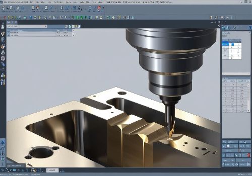
Simulation: Your First Line of Defense
Before any code ever touches a machine, it should be simulated. Modern CAM software provides powerful simulation capabilities that display the exact toolpath the machine will follow. Verify:
-
No unexpected rapid moves through the part or fixture
-
Tool clearance during tool changes and positioning moves
-
Arc motions are properly formed
-
Tool engagement matches expectations
For critical programs, use a digital twin—a virtual replica of your specific machine model with accurate dimensions—to detect collisions that generic simulation might miss.
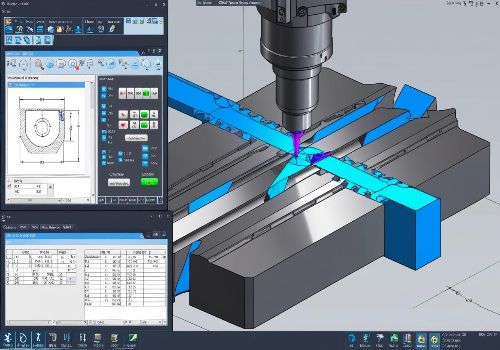
Backplotting: The Programmer’s X-Ray
Backplotting software reads G-code and renders the resulting toolpath without requiring the original CAM file. This is invaluable for:
-
Verifying posted code matches intended toolpath
-
Troubleshooting existing programs when CAM files are unavailable
-
Checking arc directions and plane selection
Popular options include NCViewer (free web-based), CIMCO Edit, and Predator Editor.
G-Code Post-Processors: The Critical Link
Many errors originate in the post-processor—the software that converts CAM toolpaths into machine-specific G-code. Ensure your post-processor is:
-
Machine-specific (different controls interpret code differently)
-
Up-to-date with your machine’s current configuration
-
Properly configured for your machine’s options (coolant, tool changers, etc.)

Phase 2: Systematic Error Diagnosis
When an error does occur, follow this structured approach:
Step 1: Observe Without Panic
When the machine stops with an alarm or produces a bad part:
-
Record the exact error message and alarm number from the control
-
Note the line number or block number displayed (not all controls show this)
-
Observe the machine’s position when the error occurred
-
Check any recently changed variables (work offsets, tool offsets, parameters)
Pro tip: Most CNC controls have an alarm history log. Learn how to access it on your machine.
Step 2: Replay and Isolate
The most powerful troubleshooting technique is the replay-and-isolate method:
-
Restart the program from the beginning if safe to do so
-
Run the program in single-block mode (pressing cycle start for each line)
-
Watch the machine carefully—note where the problem begins
-
Record the block number where the first sign of trouble appears
-
Run the program again from a safe block before the suspected problem area
Never assume the problem is exactly where the machine stopped. The error may have occurred earlier, with the machine only detecting it when a later condition triggered the alarm.
Step 3: Block-by-Block Verification
Once you’ve isolated the problematic blocks, verify each code:
Check motion commands:
-
Is G00 or G01 active? (rapid vs. feed)
-
Is F (feedrate) appropriately set and not zero?
-
Are coordinates within machine travel limits?
-
Are I, J, K values correct for arc centers?
Check preparatory commands:
-
Is G90 (absolute) or G91 (incremental) set correctly?
-
Is G17 (XY plane), G18 (XZ), or G19 (YZ) appropriate for the operation?
-
Are cutter compensation (G41/G42) commands paired with G40 correctly?
Check tooling commands:
-
Does T code match a tool in the magazine?
-
Is M06 properly formatted for your machine?
-
Are H (length offset) and D (diameter offset) numbers valid?
Step 4: Common Error Patterns and Fixes
Missing Decimal Point
-
Symptom: Machine moves unexpectedly small or large distances
-
Example:
X1instead ofX1.0(machine may read as X0.0001 or X0.00001 depending on control) -
Fix: Always use decimal points; some controls require them for values ≥1.0
Arc Errors (Alarm: “Invalid I,J,K”)
-
Symptom: Alarm on G02/G03 block; machine won’t cut arc
-
Common causes:
-
Start and end radius differ by more than allowable tolerance
-
Incorrect plane selection (using I,J on G18 instead of I,K)
-
Incremental I,J,K values when absolute mode is active
-
-
Fix: Use CAM-generated arc moves; verify radius calculation
Radius Too Small Alarm
-
Symptom: Alarm on G41/G42 cutter compensation block
-
Cause: Tool radius larger than the arc being cut (internal corner)
-
Fix: Use smaller tool, add a larger radius to the corner, or program without compensation
Reference Return Errors
-
Symptom: G28 or G30 moves to unexpected position
-
Cause: Intermediate point coordinates not absolute, or machine-specific behavior
-
Fix: Use G91 G28 Z0 (return Z axis first, then X and Y) as a safer pattern
Phase 3: Safe Testing Before Production
After identifying and correcting potential errors:
Dry Run (No Material)
Run the program with the workpiece removed (or raised above the part) to verify:
-
All tool changes clear the workpiece and fixtures
-
No rapid moves crash into clamps or vises
-
Coordinate movements match expectations
Single-Block Execution
For new or modified programs, run the first few operations in single-block mode:
-
Press cycle start for each line individually
-
Observe each movement before continuing
-
Verify tool approach, cutting, and retract sequences
Reduced Feedrate Override
When ready to cut material:
-
Set feedrate override to 5-10% for the first pass
-
Watch the tool engagement carefully
-
Gradually increase feedrate as confidence builds
First Article Inspection
After machining the first part:
-
Inspect all critical dimensions
-
Compare to print or CAD model
-
Document any deviations
-
Adjust offsets or code as needed
Error-Specific Troubleshooting Guide
Syntax Errors
Symptom: Control displays alarm immediately or at a specific block
Common syntax errors:
-
Missing decimal point in coordinate or F value
-
Invalid character (O instead of 0, I instead of 1)
-
Extra characters after M02/M30
-
Missing G90/G91 before absolute/incremental moves
Solution: Use a code editor with syntax highlighting. Many CAM systems can verify syntax before posting.
Tool Length and Diameter Offset Errors
Symptom: Part dimensions wrong; tool machines too deep or shallow; walls off-size
Troubleshooting checklist:
-
Is the H (length offset) number correct for the active tool?
-
Is the D (diameter offset) number correct for the active tool?
-
Were the offsets measured correctly and entered properly?
-
Is wear compensation (wear offset) zero or properly set?
-
Did you call the offset before the first cutting move? (G43 H__)
Pro tip: After a tool change, always call length compensation on the same line as the first positioning move: T02 M06; G00 G90 G54 X0 Y0 S5000 M03; G43 H02 Z1.0;
Work Offset Errors
Symptom: Features machined in wrong location; machine moves to unexpected positions
Troubleshooting checklist:
-
Is G54-G59 (or extended offsets) active?
-
Have you set the work offset values correctly?
-
Did you accidentally change offsets between operations?
-
Is G90 (absolute) active? (G91 incremental would compound positions)
Critical safety note: Some controls default to G91 (incremental) on startup. Always include G90 at the beginning of your program.
Arc and Radius Errors
Symptom: Alarm on G02/G03 block; “Radius Difference Too Large” or “Invalid I,J,K”
Troubleshooting:
-
Check that you’re using the correct plane (G17 for XY; I,J for XY arcs)
-
For full circles (360°), use I,J,K with no X,Y endpoint; for partial arcs, ensure endpoint radius matches start point radius
-
CAM-generated code is generally more accurate than hand-coded arcs
Manual code tip: For 90° arcs, calculate I,J from start point to arc center, not from center to tool position.

Building Your Troubleshooting Toolkit
Essential Software Tools
| Tool | Purpose | Free/Paid |
|---|---|---|
| NCViewer | G-code backplotting | Free |
| CIMCO Edit | Editor with backplot, DNC, compare | Paid |
| Notepad++ with G-code plugin | Syntax highlighting | Free |
| Machine simulation software | Digital twin collision detection | Paid (varies) |
Essential Machine Panel Knowledge
Know where to find on your control:
-
Alarm history (usually a dedicated button or menu)
-
Current program block (often displayed on main screen)
-
Current position display (absolute, machine, relative)
-
Single-block switch (often a physical switch or soft key)
-
Feedrate and spindle overrides (critical for safe testing)
Preventing Recurring Errors: Process Improvement
Establish a Program Release Protocol
Implement a formal process before any program runs on the machine:
-
CAM verification (toolpath simulation)
-
Post-processor check (backplot the G-code)
-
Peer review (second set of eyes on critical programs)
-
Process sheet verification (tools, speeds, feeds, work offsets)
-
Dry run on machine (air cutting only)
Document Error Patterns
Maintain a troubleshooting log for your shop, noting:
-
Error code and message
-
Machine and control type
-
Root cause
-
Solution applied
Over time, this becomes an invaluable resource for training and quick reference.
Conclusion: Systematic Troubleshooting Wins
CNC code errors are inevitable, but they don’t have to be catastrophic. By following a methodical process—observe, isolate, analyze, correct, verify—you can resolve issues quickly and confidently.
The key principles to remember:
-
Never assume the error location is exactly where the machine stopped
-
Use single-block mode to watch the machine’s every move
-
Test new programs safely—dry run, single-block, reduced feed
-
Verify, don’t assume—simulate and backplot before cutting material
-
Learn from each error—document and share solutions
With practice and discipline, troubleshooting becomes not a dreaded interruption but a manageable, even routine, part of CNC programming. The most successful machinists don’t avoid errors—they just know exactly how to fix them when they occur.
Need help with CNC programming or troubleshooting? [Contact our applications engineering team] for expert support with your most challenging machining projects.