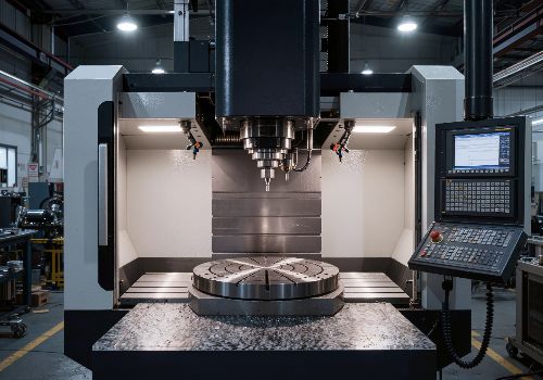
Using macros in CNC programming means employing variables, conditional logic, and mathematical expressions to create flexible, reusable programs that can adapt to changing conditions without rewriting code. Macros transform static G-code into dynamic instructions capable of handling families of parts, custom canned cycles, complex geometries, and in-process adjustments—unlocking capabilities that standard programming simply cannot achieve.
Introduction: Moving Beyond Static Code
Standard G-code is rigid. Every movement is absolute: “Go to X1.0 Y2.0,” “Drill to Z-0.5,” “Feed at 10 inches per minute.” If part dimensions change, if material hardness varies, if tolerance requirements tighten—the entire program must be rewritten.
Macros change this paradigm entirely. By introducing variables, logic, and mathematics into CNC programs, macros allow a single program to adapt to different conditions automatically.
Think of standard G-code as a paper map: fixed, static, requiring a new map for every destination. Think of macros as a GPS: you input your destination, and the system calculates the route dynamically, adapting to traffic, road conditions, and preferences.
Macros are not new—they have been available on CNC controls for decades, often as an optional feature requiring purchase from the machine tool builder. However, for shops that invest in this capability, macros unlock a level of efficiency and flexibility that provides genuine competitive advantage.
What Exactly Is a CNC Macro?
A macro is any routine or subprogram that can be run multiple times with different parameters. At its simplest level, a macro is a container that holds a value—similar to a variable in any computer programming language.
Key Components of Macro Programming
| Component | What It Does | Example |
|---|---|---|
| Variables | Store values (numbers, positions, flags) | #100=2.5 (stores 2.5 in variable #100) |
| Arithmetic | Perform calculations | #101=#100+0.5 (adds 0.5 to #100) |
| Conditional Tests | Make decisions | IF [#100 GT 0.0] GOTO 1000 (if true, go to N1000) |
| Loops | Repeat code blocks | WHILE [#100 LT 10.0] DO1 (repeat while condition true) |
| System Variables | Access machine status | #5001 reads current X-axis position |
Variable Types and Scope
Not all variables behave the same way. Understanding variable scope is critical to writing macros that work reliably.
| Variable Range | Scope | Persistence | Typical Use |
|---|---|---|---|
| #1-#33 | Local to current program | Cleared when program ends | Temporary calculations, passed arguments |
| #100-#199 | Local to program/channel | Cleared at power-off | Working variables within a program |
| #500-#999 | Global across control | Retained indefinitely | Shared data across programs |
| #1000+ | System variables | Read-only or write | Machine status, position data |
Critical distinction: A null variable (no value) is not the same as a variable containing zero. Null means the container is empty. This distinction matters when debugging macros that fail unexpectedly.
The Interpreter Nature of Macros
Custom macro is an interpreter-based language, meaning that all CNC G-code and macro commands are executed as the CNC comes across them, line by line. This is fundamentally different from compiled languages like C++ or Python, where syntax errors prevent execution altogether. With macros, an error may only appear when the control reaches that specific line during operation.
This interpreter behavior has important implications:
-
Errors can occur deep into a long-running program
-
Testing and simulation become even more critical
-
Single-block mode is invaluable for debugging
Core Macro Programming Concepts
Variables: The Foundation
Variables store values that can be read, written, and manipulated throughout the program. In FANUC-style macro syntax, variables are denoted by the # symbol followed by a number.
#100 = 1.5     (Assigns 1.5 to variable #100)
#101 = #100    (Assigns value of #100 to #101)
#102 = #101 + [2.0 * 3.0]  (Mathematical expression)
Variables can store:
-
Numeric values (dimensions, coordinates, counters)
-
Machine positions (via system variables)
-
Tool offset values
-
Conditional flags (1 for true, 0 for false)
Mathematical Operations
Macro programming supports standard arithmetic and trigonometric functions:
| Operation | Syntax (FANUC-style) | Example |
|---|---|---|
| Addition | #100 = #101 + #102 | #100 = 2.5 + 1.5 (results in 4.0) |
| Subtraction | #100 = #101 – #102 | #100 = 5.0 – 2.0 (results in 3.0) |
| Multiplication | #100 = #101 * #102 | #100 = 2.5 * 2.0 (results in 5.0) |
| Division | #100 = #101 / #102 | #100 = 10.0 / 2.0 (results in 5.0) |
| Sine | #100 = SIN[#101] | #100 = SIN[30] (results in 0.5) |
| Cosine | #100 = COS[#101] | #100 = COS[60] (results in 0.5) |
| Square Root | #100 = SQRT[#101] | #100 = SQRT[16] (results in 4.0) |
| Round | #100 = ROUND[#101] | #100 = ROUND[3.14159] (results in 3.0) |
Critical rounding note: The control stores decimal numbers as binary values. As a result, numbers stored in variables can be off by 1 least significant digit. For example, the integer 7 stored in #10000 might later read as 7.000001 or 6.999999. This can cause IF [#10000 EQ 7] statements to fail unexpectedly. The safer approach is to use IF [ROUND[#10000] EQ 7].
Conditional Statements: Giving the Program Brains
Conditional statements allow the program to make decisions based on current conditions.
IF Statement (Conditional Branching)
The IF statement tests a condition and branches to a specified line number if the condition is true:
IF [#100 LE 0.0] GOTO 1100
This reads: “If variable #100 is less than or equal to 0.0, jump to line N1100.” If the condition is false, execution continues to the next line.
Common conditional operators:
-
EQ— Equal to -
NE— Not equal to -
GT— Greater than -
GE— Greater than or equal to -
LT— Less than -
LE— Less than or equal to
WHILE Loop (Conditional Repetition)
The WHILE loop repeats a block of code as long as a condition remains true:
WHILE [#100 GT 0.0] DO1
    (Code to repeat)
    #100 = #100 - #101
END1
This structure is particularly valuable for repetitive passes—facing, roughing, or multiple-hole patterns.
GOTO and Looping: Flow Control
The GOTO statement provides unconditional branching, sending execution to a specified line number regardless of any condition:
GOTO 1000 (Jump to line N1000)
When combined with conditional IF statements and counters, GOTO creates powerful loops.
Basic loop structure:
#100 = 1.5   (Starting radius)
#101 = 0.2   (Depth of cut per pass)
N1000 (Loop start)
    (Machining code using #100)
    #100 = #100 - #101   (Reduce radius by depth of cut)
    IF [#100 GT 0.0] GOTO 1000   (Loop until radius reaches zero)
This structure allows a single program to execute multiple roughing passes automatically. The code for a single pass is written once, and the loop repeats it with incremental depth changes.

Macro Subprogram Calls: Passing Parameters
A powerful feature of macro programming is the ability to call subprograms and pass variables as arguments. This creates reusable code modules—macros that can be called again and again with different inputs.
G65 Macro Call Syntax
The G65 command calls a macro subprogram and passes variables:
G65 P2000 X1.5 Y2.0 Z-0.5 F10.0
Where:
-
P2000specifies subprogram O2000 -
X,Y,Z,Fare arguments passed to the macro
Inside the macro (O2000), these arguments are automatically assigned to local variables:
| Argument | Local Variable |
|---|---|
| A | #1 |
| B | #2 |
| C | #3 |
| D | #7 |
| F | #9 |
| X | #24 |
| Y | #25 |
| Z | #26 |
This allows a single macro to service countless calling programs with different data.
Practical Example: Custom Drill Cycle
Imagine creating a custom drill cycle for a tool that both drills and spotfaces. The macro call might look like:
G123 X#578 Y#579 R-47.0 Z-70.5 A3000.0 W-72.45 B500.0
Inside the macro, the arguments become:
-
X#578,Y#579—hole center coordinates -
R-47.0—rapid plane position -
Z-70.5—final drill depth -
A3000.0—drilling feed rate -
W-72.45—spotface depth -
B500.0—spotface feed rate
This user-created canned cycle works just like built-in cycles (G81-G89), including support for G98 and G99 return behaviors and cancellation with G80.
Practical Applications of CNC Macros
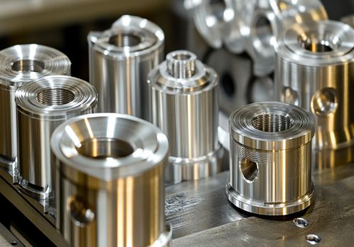
1. Families of Parts
When part families share identical features but differ in dimensions, a single macro can machine the entire family.
Example—Bolt Hole Circle Macro:
O1000 (Bolt Hole Circle Macro)
(Arguments: X=center X, Y=center Y, Z=depth, R=radius, A=start angle, B=end angle, C=count)
#10 = #24   (Store X center)
#11 = #25   (Store Y center)
#12 = #18   (Store radius)
#13 = #1    (Store start angle)
#14 = #2    (Store end angle)
#15 = #3    (Store number of holes)

#16 = [#14 - #13] / [#15 - 1]   (Calculate angle increment)

#17 = 0
WHILE [#17 LT #15] DO1
    #18 = #13 + [#17 * #16]   (Current angle)
    #20 = #10 + [#12 * COS[#18]]   (X position)
    #21 = #11 + [#12 * SIN[#18]]   (Y position)

    G00 X#20 Y#21
    G83 Z#26 R2.0 Q0.5 F5.0
    G80

    #17 = #17 + 1
END1
M99
With one macro, any bolt circle—any radius, any angle, any number of holes—can be machined by simply changing the passed arguments.
2. Custom Canned Cycles
Standard canned cycles (G81-G89) provide fixed behaviors. Macros allow creation of custom cycles for specialized tooling.
Applications for custom cycles:
-
Porting tools (combination drill/spotface)
-
Special tapping cycles with custom dwell patterns
-
Probing routines for part verification
-
Tool change macros with integrated length measurement
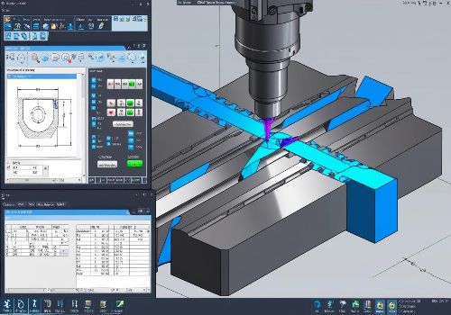
3. Probing and In-Process Inspection
Macros are essential for probing operations. A probe macro can:
-
Determine unknown part dimensions for machining
-
Set tool offsets and wear values automatically
-
Inspect castings before machining to verify material allowance
-
Verify parallelism, flatness, and location after machining
The macro reads the probe trigger position via system variables, performs calculations, and updates work offsets or tool offsets automatically—all without operator intervention.
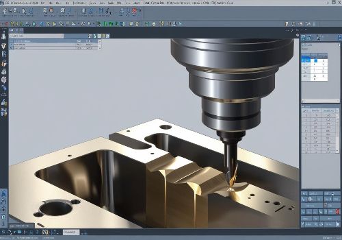
4. Complex Geometry Machining
Macros enable machining of mathematically defined shapes that would be impossible or impractical with standard G-code.
A 2026 academic study developed a universal macro template for machining ellipses, hyperbolas, and parabolas using a unified polar coordinate equation. This single macro can machine any of the three conic curve types by simply changing input parameters—dramatically reducing programming time for complex shapes.
This approach is particularly valuable on CNC lathes, where non-circular curves cannot be programmed with basic G-code and require macro programming.
5. Automatic Offset Setting
Macros can access and modify system variables for work offsets (#2001-2800 range on Haas controls) and tool offsets. This enables programs to automatically adjust for:
-
Tool wear (compensating within tolerance limits)
-
Thermal growth (adjusting based on temperature sensor readings)
-
Material variation (adjusting based on in-process measurement)
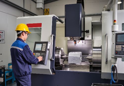
6. Semi-Automated Setup Procedures
Macros can assist operators in setup procedures. For example, a macro could drill standard clamp bolt hole patterns at any location and angle specified by the operator:
G65 P2000 Xnnn Ynnn Znnn Annn
Where X, Y, Z provide the position and A provides the rotation angle. The macro handles all the math to correctly position the pattern—the operator simply jogs to the desired location and runs the macro.
Advanced Macro Considerations
Look-Ahead and Block Processing
The control attempts to process as many lines as possible ahead of time to speed up execution. This includes the interpretation of macro variables. While this normally speeds processing, it can cause problems when sequential operations depend on state changes.
Example problem:
#12012 = 1
G04 P1.0
#12012 = 0
This is intended to turn on an output, wait 1 second, then turn it off. However, look-ahead can cause the output to turn on then immediately back off while the control processes the dwell.
Solution (using G103 P1 to limit look-ahead to one block):
G103 P1   (Limit look-ahead)
#12012 = 1
G04 P1.0
#12012 = 0
Debugging Macro Programs
Macros introduce complexity that standard G-code lacks. Effective debugging requires:
-
Single-block execution to see each line’s effect
-
Variable monitoring via the control’s variable display page
-
Block delete for debugging: When a block delete token “/” is used, the line will block look-ahead even if Block Delete mode is not active—useful for macro debugging
-
MDI testing of suspect macro blocks before full program execution
The Importance of Code Reusability
Once a macro is written and proven, it becomes a reusable asset. Human errors are inevitable, but when we use proven systems—reusable code that has been thoroughly tested—we increase our ability to perform consistently.
A well-designed macro library represents intellectual property that:
-
Reduces programming time for future projects
-
Standardizes machining approaches across the shop
-
Codifies years of machining expertise into executable code

Practical Example: The “Poor Man’s” G71 Roughing Cycle
Some CNC controls lack the G71 rough turning cycle. Using macros, machinists can create their own roughing cycle.
The concept:
-
Store current material radius in a variable (#100)
-
Store desired depth of cut in a variable (#101)
-
Use G52 coordinate shift to offset the profile
-
Loop until material radius is reduced to zero
(G71 Replacement using Macro)
#100 = 1.5   (Starting radius)
#101 = 0.2   (Depth of cut)

N1000 (Loop start)
G52 X#100   (Shift coordinate system by current radius)

IF [#100 LE 0.0] GOTO 1100   (Exit when done)

M97 P10   (Call profile subprogram)
#100 = #100 - #101   (Reduce radius)
GOTO 1000   (Repeat loop)

N1100

. . . (Rest of program)
M30

N10 (Profile subprogram)
    G01 X0 Z0 F0.01
    G01 Z-1.0
    G01 X1.0 Z-1.5
    G01 Z-2.0
    G00 X1.5
    M99
Each loop shifts the profile inward by the depth of cut and machines another pass.
Which Controls Support Macro Programming?
Most major CNC control manufacturers offer macro programming capabilities, though they use different names and syntax variations:
| Manufacturer | Feature Name |
|---|---|
| FANUC | Custom Macro B |
| Haas | User-Definable Macros |
| Siemens | Parameter Programming |
| Heidenhain | Q Parameter Programming |
| Mazak | Mazak Macro |
Macro programming is often an optional feature requiring an additional purchase. Check with your machine tool builder or control distributor to verify capability before investing development time.
Learning Resources for Macro Programming
For those ready to develop macro skills, several pathways exist:
-
FANUC Academy offers courses titled “CNC & Macro’s Programming Milling” and “CNC & Macro’s Programming Turning“
-
Machine manufacturer documentation provides syntax specific to your control (Haas has thorough macro documentation in their operator manuals)
-
Industry publications like Modern Machine Shop publish regular column features on macro programming
-
Online communities and forums where experienced programmers share techniques
Conclusion: Macros as a Strategic Capability
Macro programming transforms CNC programming from static code into dynamic, intelligent instructions. The benefits are substantial:
-
Flexibility—one program machines entire part families
-
Efficiency—reusable code reduces programming time
-
Accuracy—proven code eliminates manual recalculations
-
Automation—macros handle repetitive calculations and decisions
-
Differentiation—custom cycles provide capability competitors may lack
The investment in learning macro programming pays dividends across every project. A single well-designed macro can replace dozens of individual programs, reduce setup time, and eliminate the errors that come from manual reprogramming.
For shops serious about advancing their CNC capabilities, macro programming is not an optional add-on—it is a core competency that separates commodity machining from precision manufacturing.
Ready to unlock the full potential of your CNC equipment? [Contact our applications engineering team] to discuss how macro programming can automate your complex machining challenges.