Quick Answer
An O-ring groove should be designed around the complete sealing system, not only the O-ring diameter.
The groove must provide:
- The correct amount of squeeze
- Enough volume for the elastomer
- Suitable width and depth
- Controlled corner radii
- Acceptable extrusion clearance
- A surface finish compatible with the seal
- Reliable installation and inspection conditions
The first design question is whether the seal is static or dynamic.
A stationary face seal, piston seal, and rotating shaft seal do not automatically use the same groove design.
For a reliable CNC machining RFQ, specify the O-ring size, cross-section, material, pressure, temperature, motion, groove location, squeeze requirement, surface finish, and inspection needs.
Exact groove dimensions should come from the selected O-ring and application-specific design data rather than a generic rule.
What Is an O-Ring Groove?
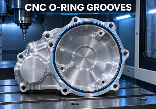
An O-ring groove, also called a gland, is the machined cavity that holds an elastomeric O-ring between two mating surfaces.
The groove must keep the O-ring located while allowing it to deform enough to seal against the mating surfaces.
Important groove features include:
- Groove depth
- Groove width
- Groove diameter or centerline
- Corner radius
- Lead-in chamfer
- Surface finish
- Clearance to the mating surface
- Pressure-side orientation
The groove may be machined into:
- Aluminum covers
- Stainless steel housings
- Carbon-steel blocks
- Pistons
- Shafts
- Flanges
- Hydraulic components
- Custom motorcycle parts
Why Static and Dynamic O-Ring Grooves Are Different
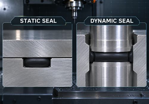
A static seal has little or no relative movement between the O-ring and mating surfaces.
Examples include:
- Cover gaskets
- Flange seals
- Plug seals
- Housing joints
- Inspection covers
A dynamic seal experiences reciprocating, rotating, or oscillating movement.
Examples include:
- Piston seals
- Rod seals
- Rotating shaft seals
- Moving actuators
Dynamic applications are generally more sensitive to:
- Friction
- Lubrication
- Surface finish
- Extrusion clearance
- Heat
- Groove geometry
- Seal wear
A groove that works for a stationary cover may create excessive friction or wear in a moving application.
Start With the Correct O-Ring Specification
Before modeling the CNC groove, confirm the O-ring itself.
The design should identify:
- O-ring inside diameter
- O-ring cross-section
- Standard or size series
- Elastomer material
- Hardness, if important
- Temperature range
- Fluid or chemical exposure
- Pressure range
- Static or dynamic use
- Installation direction
The O-ring cross-section is especially important because it controls the approximate groove depth and width.
Do not choose the groove first and then attempt to find an O-ring that fits unless the design intentionally uses a custom seal.
How O-Ring Squeeze Affects Groove Depth
O-ring squeeze is the amount by which the seal cross-section is compressed after the mating surfaces are assembled.
For a simple axial or face seal, the approximate relationship is:
Squeeze percentage = (O-ring cross-section − gland depth) ÷ O-ring cross-section × 100
For a radial seal, the calculation uses the relevant radial gland dimension and mating diameter.
The goal is enough compression to maintain sealing contact without creating excessive friction, heat, installation force, or elastomer damage.
Published seal-design guidance commonly separates static and dynamic squeeze ranges. Apple Rubber provides general guidance of approximately 10–40% for static applications and no more than 30% for dynamic applications, while emphasizing that final values depend on the application. Apple Rubber O-ring installation guidance
These ranges should be treated as general guidance, not a substitute for the O-ring manufacturer’s design table for the selected material and service conditions.
How Groove Volume Affects Sealing Reliability
The O-ring must have enough available volume inside the gland to accommodate:
- Thermal expansion
- Pressure effects
- Material deformation
- Assembly variation
- Tolerance stack-up
If the groove is too shallow or too narrow, the O-ring may be over-compressed.
Possible results include:
- High assembly force
- Excessive friction
- Accelerated wear
- Nicks during installation
- Elastomer extrusion
- Difficulty closing the joint
If the groove is too large, the O-ring may not receive enough squeeze or may move inside the gland.
The groove should be evaluated by comparing O-ring volume with available gland volume, not by checking depth alone.
Groove Width and Side Clearance
Groove width affects how freely the O-ring can deform and whether it can move under pressure or during installation.
A groove that is too narrow may pinch the seal.
A groove that is too wide may allow excessive movement, rolling, or extrusion, particularly in dynamic applications.
The correct width depends on:
- O-ring cross-section
- Static or dynamic service
- Pressure
- Temperature
- Backup-ring use
- Diametral clearance
- Installation method
- Required squeeze
For high-pressure systems, a backup ring or a different seal design may be needed instead of simply reducing groove clearance.
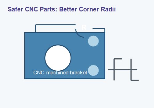
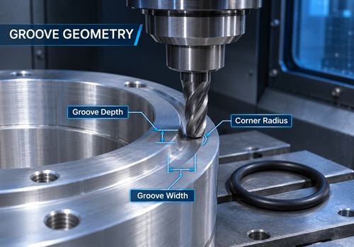
Corner Radii and Edge Breaks for CNC-Machined Grooves
Sharp groove corners can damage an O-ring during installation or create stress concentrations in the machined component.
The drawing should control:
- Internal groove radius
- Entry chamfer
- Edge break
- Burr removal
- Transition between the groove and adjacent surface
The radius must be large enough for the O-ring and tool geometry, but it should not interfere with the intended compression area.
For a CNC-machined groove, the radius also affects cutter selection.
A small internal radius may require:
- A smaller end mill
- Slower machining
- Extra finishing passes
- More tool deflection control
- Additional inspection
If the design allows a larger radius without affecting the seal, the change may improve machining stability and reduce cost.
Surface Finish Requirements
The O-ring seals against the mating surfaces and groove walls.
Surface defects can create leakage paths or damage the elastomer during installation and movement.
Important surface concerns include:
- Tool marks running across the sealing path
- Burrs at the groove entry
- Sharp scratches
- Chatter marks
- Porosity or surface damage
- Excessive roughness
- Inconsistent coating thickness
Dynamic sealing surfaces usually require more careful control than static surfaces because the seal slides or rotates against them.
The correct finish depends on:
- Elastomer type
- Pressure
- Motion
- Lubrication
- Temperature
- Manufacturer guidance
The drawing should identify the sealing surface and apply the finish requirement only where it matters.
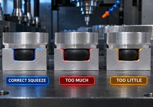
O-Ring Compression: Too Much Versus Too Little
The groove should provide controlled compression rather than maximum compression.
Too Much Squeeze
Excessive compression may cause:
- High friction
- Difficult assembly
- Heat generation
- Premature wear
- Seal cutting
- Permanent deformation
- Reduced dynamic performance
Too Little Squeeze
Insufficient compression may cause:
- Leakage at low pressure
- Seal movement
- Loss of sealing after thermal cycling
- Poor compensation for surface variation
- Increased sensitivity to tolerance stack-up
The design should consider the minimum and maximum assembled conditions, not only nominal CAD dimensions.
Pressure, Clearance, and Extrusion Risk
As pressure increases, the O-ring may be pushed into the clearance gap between mating components. This is called extrusion.
Extrusion risk depends on:
- Pressure level
- Pressure spikes
- O-ring hardness
- Temperature
- Diametral clearance
- Groove support
- Surface condition
- Backup-ring use
If the application has high pressure, pressure cycling, or a large clearance gap, the supplier may recommend:
- A harder elastomer
- A backup ring
- Tighter clearance
- A different seal geometry
- Additional support
Do not solve an extrusion problem only by increasing squeeze. Excessive squeeze can create friction and installation problems without addressing the clearance condition.
Static O-Ring Groove Design Considerations
For static seals, the main design priorities are usually:
- Stable squeeze
- Correct gland volume
- Controlled surface finish
- Adequate corner radius
- Limited extrusion clearance
- Reliable installation
- Protection from cutting or pinching
Static grooves are often used in:
- CNC-machined covers
- Flanges
- Housings
- Hydraulic blocks
- Engine covers
- Battery boxes
- Inspection ports
The O-ring should be compressed evenly around the sealing path.
Uneven joint closure, tilted covers, or poor bolt patterns can create leakage even when the groove dimensions are correct.
Dynamic O-Ring Groove Design Considerations
For dynamic seals, friction and wear become major design factors.
The design should review:
- Sliding or rotating speed
- Lubrication
- Surface finish and direction
- Seal stretch
- Groove clearance
- Pressure direction
- Thermal expansion
- O-ring hardness
- Installation damage
Dynamic grooves may require more careful control of lead-in geometry and surface transitions.
A sharp edge can cut the O-ring during installation or movement.
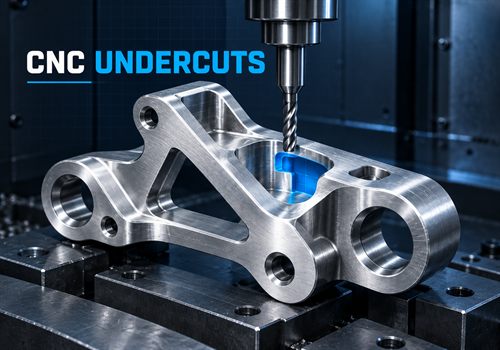
CNC Machining the O-Ring Groove
When preparing the part for CNC machining, the supplier should check:
- Cutter diameter
- Tool access
- Groove depth
- Groove width
- Internal corner radius
- Tool deflection
- Surface finish
- Burr removal
- Workholding
- Inspection access
A very narrow or deep groove may require a small cutter with limited stiffness.
If the design allows a larger radius or wider groove without affecting the seal, the change may improve machining stability and reduce cost.
The groove should also be positioned so the tool can reach it without damaging adjacent sealing surfaces.
O-Ring Groove Design for Aluminum Parts
Aluminum is common for CNC-machined sealing covers and housings because it is lightweight and easy to machine.
However, designers should consider:
- Surface coating thickness
- Thread or fastener loads near the groove
- Groove edge strength
- Local wall thickness
- Galvanic or chemical exposure
- Anodizing or plating effects
- Risk of burrs and raised edges
If the part will be anodized, coated, or painted, confirm whether the coating will be applied to the groove and how its thickness affects squeeze and fit.
What Should Be Included in an O-Ring Groove RFQ?
An accurate CNC machining RFQ should include:
- 3D CAD model
- 2D drawing with groove section views
- O-ring size or cross-section
- O-ring material and hardness
- Static or dynamic application
- Pressure and temperature range
- Fluid or chemical exposure
- Groove width and depth, if already defined
- Required squeeze or seal standard
- Surface-finish requirements
- Corner-radius and edge-break requirements
- Material and coating
- Quantity and expected repeat orders
- Leak-test or inspection requirements
If the groove dimensions are not finalized, provide:
- O-ring part number or cross-section
- Application type
- Pressure
- Temperature
- Fluid or chemical exposure
- Mating geometry
- Quantity
The CNC supplier can then review the gland design before machining.
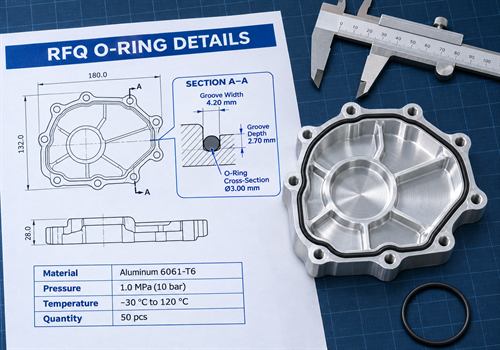
Example: A CNC-Machined Motorcycle Engine Cover
Imagine a CNC-machined aluminum engine cover that uses an O-ring around its perimeter.
The groove design should account for:
- O-ring cross-section
- Static face-seal use
- Cover bolt spacing
- Joint flatness
- Groove depth and width
- Corner radii at cover transitions
- Surface finish along the sealing path
- Coating or anodizing thickness
- Maximum pressure and temperature
If the groove is too shallow, the cover may be difficult to close and the O-ring may be over-compressed.
If the groove is too deep, the seal may not receive enough squeeze and may leak during vibration or thermal cycling.
The most efficient approach is to confirm the O-ring specification first, select the design table for the application, and then review the final groove with the CNC supplier.
How to Reduce the Cost of CNC O-Ring Grooves
You can often reduce manufacturing cost by:
- Using a standard O-ring size when the design allows it
- Avoiding unnecessarily small internal radii
- Identifying only the sealing surfaces that require special finish
- Providing a section view instead of relying only on a 3D model
- Avoiding coating requirements inside the groove unless necessary
- Sharing pressure, temperature, motion, and fluid information early
- Standardizing groove designs across a family of parts
- Asking for a design-for-machining review before production
The lowest-cost groove is not always the shallowest or narrowest one.
It is the groove that meets the sealing requirement while remaining stable to machine, inspect, finish, and assemble.
FAQ
Should Static and Dynamic O-Ring Grooves Use the Same Dimensions?
Not automatically.
Static and dynamic seals have different requirements for squeeze, friction, clearance, surface finish, lubrication, and wear.
How Deep Should an O-Ring Groove Be?
It depends on the O-ring cross-section, required squeeze, seal type, material, pressure, temperature, and clearance.
Use the selected O-ring manufacturer’s gland-design data rather than a generic depth.
Does Groove Width Affect Sealing?
Yes.
Groove width affects elastomer movement, available volume, extrusion behavior, and installation.
A groove that is too narrow or too wide can reduce reliability.
Should the Groove Have Sharp Corners?
Usually, no.
Controlled radii and edge breaks help reduce O-ring damage and make CNC machining more predictable.
The radius must still match the seal and tool geometry.
Can an O-Ring Groove Be Anodized or Coated?
Sometimes.
However, coating thickness can change groove dimensions and squeeze.
Confirm whether the coating enters the groove and include this in the design review.
What Information Should I Send for an O-Ring Groove Quote?
Send:
- 3D model
- 2D drawing
- O-ring size
- O-ring material
- Static or dynamic application
- Pressure
- Temperature
- Fluid
- Quantity
- Surface finish
- Coating
- Leak-test requirements
Final Takeaway
An O-ring groove should be designed as part of a complete sealing system.
The correct groove depends on:
- O-ring cross-section
- Squeeze
- Groove volume
- Width
- Depth
- Corner radii
- Surface finish
- Pressure
- Temperature
- Material
- Static or dynamic motion
For CNC machining, clear groove geometry also improves:
- Tool selection
- Surface finish
- Burr control
- Inspection
- Quotation accuracy
- Assembly repeatability
If you are developing a CNC-machined cover, housing, engine component, mounting part, or hydraulic block with an O-ring seal, send the 3D model, 2D drawing, O-ring specification, material, application conditions, and quantity.
Our CNC machining team can review the groove design and suggest a practical machining route for prototypes, small batches, OEM parts, and repeat production.
Have an O-ring groove that needs a manufacturing review? Send your drawing or 3D model for a practical quotation.