Quick Answer
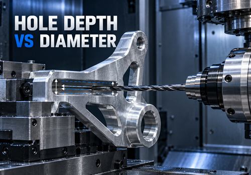
For many conventional CNC-drilled holes, a depth-to-diameter ratio of approximately 3×D to 5×D is a practical starting point for design review. Here, D means the drill diameter.
For example, a 5 mm drill producing a 25 mm hole has a ratio of 5×D.
This is a planning guideline, not a universal manufacturing limit. Actual capability depends on:
- Drill type
- Material
- Machine rigidity
- Coolant delivery
- Chip evacuation
- Hole tolerance
- Entry and exit conditions
- Blind or through-hole design
Once a hole moves beyond a conventional range, the supplier may need a long-reach or deep-hole drill, peck drilling, through-tool coolant, a pilot hole, or a secondary finishing operation.
The most practical ratio is therefore the one that meets the function without creating unnecessary process risk or cost.
What Does Depth-to-Diameter Ratio Mean?
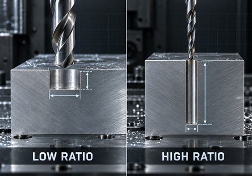
The depth-to-diameter ratio compares the effective drilled depth with the nominal hole diameter:
Depth-to-diameter ratio = hole depth ÷ hole diameter
Examples:
- 10 mm deep ÷ 5 mm diameter = 2×D
- 20 mm deep ÷ 5 mm diameter = 4×D
- 50 mm deep ÷ 5 mm diameter = 10×D
The calculation is simple, but manufacturing difficulty increases as the ratio rises.
A narrow, deep hole gives chips less room to escape and gives the tool a longer unsupported cutting length.
Why Higher Ratios Make CNC Drilling More Difficult
Chip Evacuation Becomes More Important
Drilling produces chips inside a confined channel.
In a shallow hole, chips can usually exit more easily. In a deep hole, chips can pack inside the flutes, increasing cutting force, heat, and the risk of tool damage.
Chip packing can also scratch the hole wall or cause the drill to seize.
Material type matters. Aluminum can create long, sticky chips, while stainless steel may generate work hardening and heat-related challenges.
Tool Deflection Can Affect Hole Position
As the cutting length increases, the drill becomes more sensitive to bending forces.
A long, slender drill may start to wander at entry or deflect during cutting.
Possible results include:
- Hole position error
- Diameter variation
- Tapered holes
- Poor straightness
- Chatter marks
- Breakage near the bottom of a blind hole
Heat and Coolant Delivery Become Critical
Deep holes make it more difficult to deliver coolant to the cutting edge and remove heat from the hole.
If heat remains trapped, tool wear may accelerate and the hole surface may deteriorate.
Through-tool coolant can help in some applications, but it is not a substitute for the correct drill geometry, cutting data, and chip-control strategy.
Inspection Becomes More Difficult
A deep internal hole may be difficult to measure with ordinary calipers or plug gauges.
If the hole has a tight tolerance, position requirement, or straightness requirement, the drawing should identify the inspection method before production begins.
What Is a Practical Ratio for Conventional CNC Drilling?
Around 1×D to 3×D: Generally Straightforward
This range is often easier to plan with standard drills, normal machine access, and ordinary chip evacuation.
The exact result still depends on material and tolerance, but the ratio itself is usually not the primary cost driver.
Around 3×D to 5×D: Practical but Review the Process
This is often a reasonable target for many conventional drilling applications.
Tool geometry, drill length, coolant, workholding, and the hole’s function should still be checked.
This range should be treated as a starting point for engineering discussion, not a guaranteed capability for every part.
Around 5×D to 10×D: Deep-Hole Review Recommended
At this point, the supplier should confirm whether a standard drill is appropriate.
Possible requirements include:
- Peck drilling
- Through-tool coolant
- Parabolic-flute drill
- Pilot hole
- Reduced cutting data
- Dedicated deep-hole drill
- Secondary reaming or boring
Above 10×D: Treat the Hole as a Specialized Feature
The process should be reviewed as a deep-hole application rather than assumed to be ordinary drilling.
Specialized drills can support much higher ratios, but their capability depends on the exact tool family and application.
A high-ratio tool designed for 20×D or 30×D should not be compared directly with a general-purpose twist drill.
When Should You Use a Conservative Ratio?
A lower depth-to-diameter ratio is usually preferable when the hole is:
- Close to a critical datum
- Used for a locating pin or bearing
- Required to be straight over its full depth
- Blind with a controlled bottom condition
- Located in stainless steel or another difficult material
- Close to a thin wall or edge
- Crossed by another hole
- Required to meet a tight positional tolerance
- Difficult to inspect after machining
Possible design alternatives include:
- Increasing the hole diameter if function allows
- Reducing the hole depth
- Making the hole through instead of blind
- Adding an access opening
- Splitting the component into two parts
- Using a separate insert or sleeve
- Changing the assembly sequence

How Does the Hole Type Affect the Ratio?
Through Holes
Through holes can be easier to manage because chips have an exit path.
However, breakthrough can create burrs, damage a fixture, or affect the opposite surface.
The entry and exit conditions should be considered in the drawing and workholding plan.
Blind Holes
Blind holes usually require more process control because chips and coolant must be managed within the hole.
The bottom geometry also matters. A standard twist drill may leave a conical point, so the drawing should not assume a flat bottom unless a secondary operation is specified.
Cross Holes
A drill that intersects another hole can experience an unstable cutting condition.
The drill may pull toward the open space or create an irregular breakthrough.
Cross-hole geometry should be reviewed using toolpath simulation or a process assessment.
Angled Holes
An angled entry can cause the drill to walk unless the surface is prepared with a spotface, pilot feature, or suitable tool geometry.
The effective depth and the tool’s unsupported length may also be greater than the simple drawing dimension suggests.
What Drilling Strategy May Be Needed for Deeper Holes?
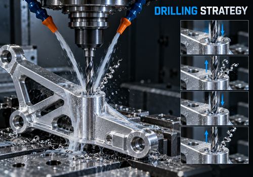
Depending on the ratio and application, the process may use:
- Peck drilling
- Through-tool coolant
- Parabolic-flute drill
- Carbide deep-hole drill
- Pilot hole
- Reduced feed or speed
- Guide bushing
- Improved workholding
- Reaming
- Boring
- Specialized gun drilling
Pecking is not automatically the best solution.
Excessive pecking can increase cycle time and may create marks or inconsistent cutting conditions.
The supplier should select the strategy based on the tool manufacturer’s recommendations and the part’s material and tolerance.
How Material Changes the Practical Ratio
Aluminum
Aluminum is often machinable, but some grades can create long or sticky chips.
Proper tool geometry, sharp cutting edges, and chip evacuation remain important for deep holes.
Stainless Steel
Stainless steel can generate more heat and may work harden if the drill rubs instead of cutting.
A stable setup and suitable cutting data are especially important.
Carbon Steel
Carbon steel varies by grade and hardness.
The supplier should review the actual material condition rather than rely only on the general material name.
Plastics and Engineering Polymers
Although the cutting force may be lower, plastics can soften, melt, deform, or produce stringy chips.
Hole diameter and depth should be reviewed together with heat control and support of the part.
How Tolerance Changes the Cost of a Deep Hole
A large depth-to-diameter ratio becomes more expensive when combined with tight requirements for:
- Diameter
- Straightness
- Cylindricity
- Positional accuracy
- Surface finish
- Concentricity
- Bottom depth
If the hole is only a clearance feature, a general tolerance may be sufficient.
If it locates a shaft or supports a bushing, additional finishing and inspection may be necessary.
Designers should avoid applying a tight tolerance to every hole by default. Specify the requirement that the assembly actually needs.
What Should Be Included in a Deep-Hole CNC RFQ?
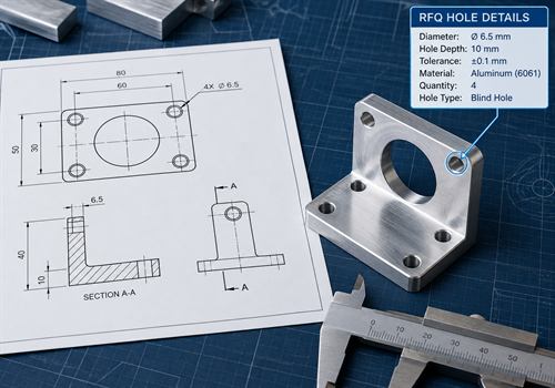
A supplier can evaluate the hole more accurately when the RFQ includes:
- Hole diameter
- Effective hole depth
- Depth-to-diameter ratio, if known
- Blind or through-hole condition
- Material and material condition
- Hole tolerance
- Position, straightness, or perpendicularity requirements
- Entry and exit surface condition
- Cross-hole or interrupted-hole information
- Thread, ream, counterbore, or countersink details
- Quantity and expected repeat orders
- Required surface finish
- Inspection method
If the exact drilling method is not known, specify the finished hole requirement and its function.
A machining supplier can then compare standard drilling, deep-hole tooling, reaming, boring, or a design revision.
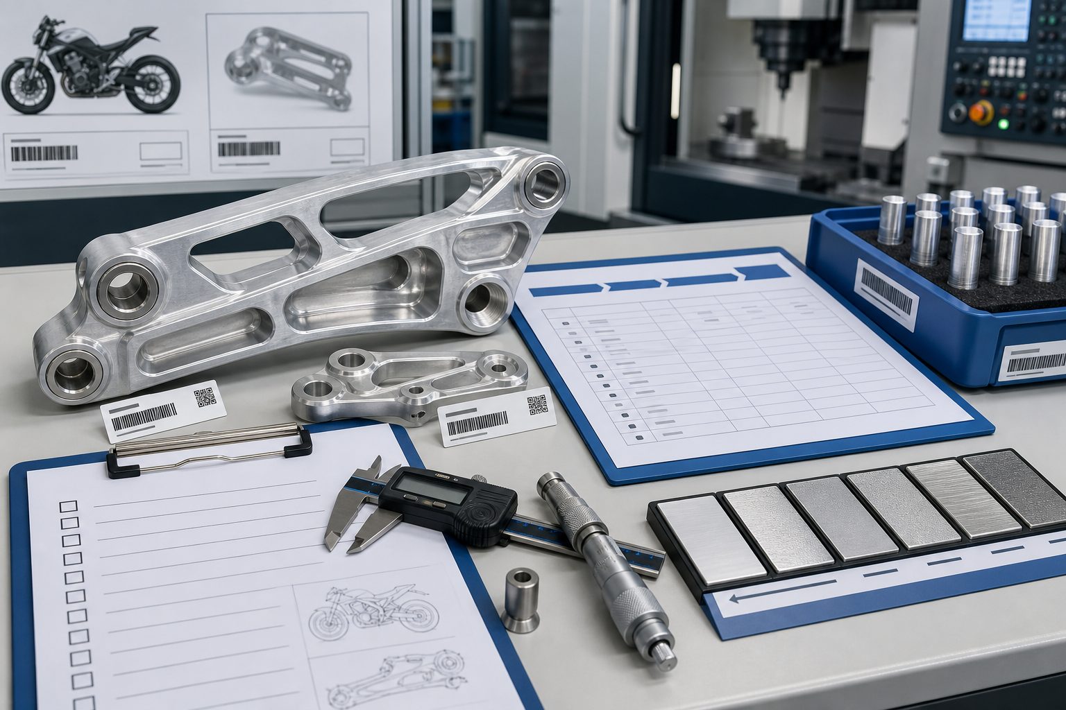
Example: A Motorcycle Bracket With a Deep Mounting Hole
Imagine an aluminum motorcycle bracket with a 6 mm hole that must be drilled 30 mm deep.
The nominal ratio is:
30 mm ÷ 6 mm = 5×D
That may be practical for a suitable drill and stable setup, but the process still depends on:
- Whether the hole is blind or through
- Whether it must be straight
- Whether it intersects another feature
- Whether the diameter is for clearance or precision fit
- Whether a special surface finish is required
If the same design changes to a 6 mm hole at 60 mm deep, the ratio becomes:
60 mm ÷ 6 mm = 10×D
That should trigger a deeper process review.
The supplier may recommend:
- Long-reach drilling
- Through-tool coolant
- Peck drilling
- A pilot hole
- A design change
- Reaming or boring
The key question is not simply:
“Can the machine reach 10×D?”
The better question is:
“Can the hole be produced repeatedly at the required quality and cost?”
How to Reduce the Cost of Deep Drilled Holes
You can often reduce cost by improving the design and RFQ before production:
- Use a larger diameter if the function allows it.
- Avoid unnecessary blind-hole depth.
- Use a through hole when assembly and appearance permit.
- Avoid tight tolerances on non-critical holes.
- Provide a clear section view.
- Identify whether the hole is for clearance, alignment, threading, or a press fit.
- Share expected annual quantity, not only the first order.
- Ask the supplier to compare drilling, reaming, boring, and design alternatives.
FAQ
What is a good general depth-to-diameter ratio for CNC drilling?
For early design review, approximately 3×D to 5×D is often a practical starting range for conventional CNC drilling.
It is not a universal limit. Material, tool, machine, coolant, tolerance, and hole type can change the result.
Is 10×D always a problem?
No.
Specialized deep-hole drills can support much higher ratios.
However, a 10×D hole should normally receive a process review instead of being treated like a routine shallow hole.
Are blind holes more difficult than through holes?
Often, yes.
Blind holes provide less chip exit space and require control of bottom depth and geometry.
The actual difficulty depends on material, tool design, coolant, and tolerance.
Can peck drilling solve every deep-hole problem?
No.
Peck drilling can help with chip evacuation, but it may increase cycle time and does not eliminate tool deflection, poor workholding, or unsuitable tool geometry.
Should I specify the drill type on my drawing?
Usually, specify the finished hole requirements first.
Let the machining supplier recommend the drill and process unless your internal standard requires a specific tool or method.
Final Takeaway
The most practical depth-to-diameter ratio for a CNC-drilled hole is not a single universal number.
For many conventional applications, 3×D to 5×D is a useful starting range.
Above that, the supplier should review:
- Tool geometry
- Chip evacuation
- Coolant
- Machine rigidity
- Material
- Tolerance
- Hole type
- Inspection requirements
The best way to control cost is to define the function of the hole, avoid unnecessary depth, use realistic tolerances, and provide enough information for the supplier to choose the right drilling strategy.
If you are planning a deep hole in an aluminum, stainless steel, or carbon-steel CNC part, send the 3D model, 2D drawing, material, quantity, hole diameter, depth, tolerance, and application details.
Our CNC machining team can review the ratio and recommend a practical production route for prototypes, small batches, OEM parts, and repeat production.
Have a deep-hole CNC project? Send your drawing or 3D model for a manufacturing review and quotation.