Quick Answer
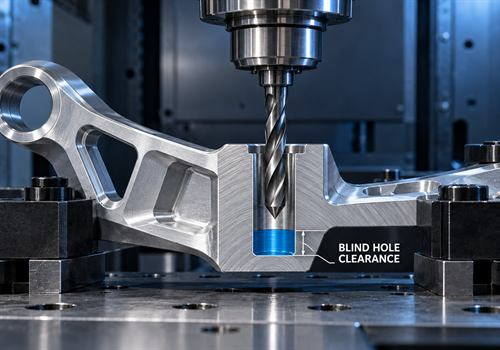
To dimension a CNC blind hole correctly, separate the required straight cylindrical depth from the additional depth occupied by the drill point.
The drawing should state:
- Hole diameter
- Usable cylindrical depth
- Total drilled depth or bottom condition
- Required tolerance
- Functional requirement
The drill-point clearance is not a universal fixed value. It depends mainly on the drill diameter and included point angle.
A useful geometric estimate is:
Drill-point height = 0.5 × hole diameter ÷ tan(point angle ÷ 2)
For example, a 6 mm hole drilled with an approximately 118° point angle has a conical point height of about 1.8 mm. A 135° point angle produces a shorter point height of approximately 1.2 mm.
Actual results can vary with drill geometry, chisel edge, tool wear, and the finishing process.
What Is Drill-Point Clearance?
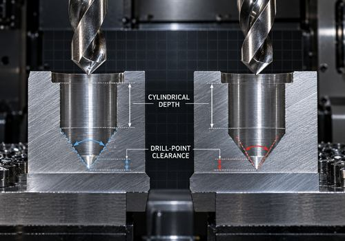
A conventional twist drill does not create a flat-bottomed hole. The cutting lips form a conical point at the bottom of the hole.
If a drawing calls for a 20 mm deep blind hole, the designer must clarify whether 20 mm means:
- 20 mm of usable cylindrical wall
- 20 mm to the drill-point apex
- 20 mm minimum total drilled depth
- 20 mm of thread depth after tapping
- 20 mm of clearance below a fastener or insert
These requirements are not interchangeable.
Why a Blind-Hole Drawing Can Create Confusion
Many manufacturing problems occur because a single depth dimension is placed beside a blind-hole symbol without identifying the intended bottom condition.
The supplier may then need to ask:
- Is the dimension to the cylindrical wall or the drill tip?
- Is the bottom cone acceptable?
- Does the mating component need a flat seat?
- Is the hole threaded?
- How much unused clearance is needed below the screw or pin?
- Is the depth a minimum, maximum, or nominal value?
If the answer is unclear, two suppliers may quote different processes while believing they are quoting the same part.
The Three Depths That Should Be Considered
1. Required Cylindrical Depth
This is the useful straight-sided portion of the hole.
It may be needed for:
- Thread engagement
- Pin location
- Bushing support
- Fastener clearance
- Shaft guidance
- Insert installation
- Adhesive or sealant volume
If the function depends on a straight cylindrical wall, dimension this depth separately.
2. Drill-Point Height
This is the conical portion produced by the drill point below the straight-sided section.
Its approximate height depends on the drill diameter and included point angle.
For an included point angle θ and hole diameter D:
h ≈ (D ÷ 2) ÷ tan(θ ÷ 2)
This is a geometric estimate, not a substitute for the actual tool drawing.
3. Total Drilled Depth
The total depth should provide enough space for the required cylindrical portion plus the drill point and any additional safety clearance.
In simple form:
Total depth ≥ required cylindrical depth + drill-point height + functional clearance
The additional clearance may be small or significant depending on the application.
How Drill-Point Angle Changes the Required Clearance
Common drill point angles are not interchangeable.
Approximate conical point heights are:
| Included Point Angle | Approximate Point Height |
|---|---|
| 118° | 0.30 × D |
| 135° | 0.21 × D |
| 140° | 0.18 × D |
| 180° flat-bottom tool | No normal conical point |
For a 6 mm hole, the approximate point height would be:
- 118° point: approximately 1.8 mm
- 135° point: approximately 1.2 mm
- 140° point: approximately 1.1 mm
The exact value should be confirmed against the selected drill or finishing tool.
Different drill types, spot drills, pilot drills, and flat-bottom tools produce different bottom geometries. For critical blind holes, the supplier should confirm the actual tool geometry before production.
How Should a Blind Hole Be Dimensioned on a Drawing?
A clear drawing normally identifies four things:
- Hole diameter
- Required cylindrical depth
- Bottom condition or total depth
- Tolerance and functional requirement
Instead of writing only:
Ø6 × 20 deep blind hole
consider specifying:
Ø6.0 +0.1 / 0 mm, 20 mm minimum full-diameter depth; drill point may extend below this depth; provide 2 mm minimum clearance below the functional seat.
The correct wording depends on the part function.
If the bottom must be flat, specify a flat-bottom operation or a subsequent machining process. A normal twist drill should not be expected to create a flat bottom.
Blind Holes for Threaded Parts
Threaded blind holes need more depth than the visible thread length alone.
The total drilled depth may need to include:
- Required full thread depth
- Tap chamfer or incomplete thread area
- Chip clearance below the tap
- Drill-point clearance below the tap-drill diameter
- Bottom safety distance
If a screw must engage 12 mm of usable thread, a 12 mm drill depth is usually not enough.
The tapping process needs room below the full thread, and the original drill point may occupy additional space.
The RFQ should state whether the specified depth refers to:
- Full thread
- Usable thread
- Total drilled depth
Blind Holes for Pins, Shafts, and Inserts
For a locating pin or small shaft, the conical drill point may reduce the effective contact length at the bottom of the hole.
If the component needs a flat stop, radial support, or controlled seating depth, consider:
- A flat-bottom drill
- Boring after drilling
- A counterbore or spotface
- A separate insert or sleeve
- A design change that moves the functional contact away from the cone
The best solution depends on tolerance, material, quantity, and inspection method.
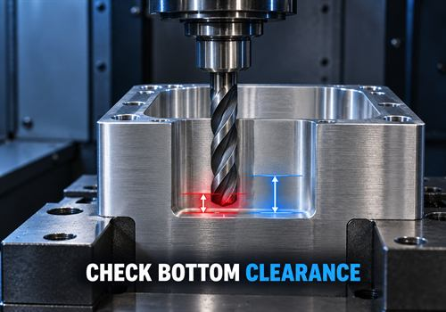
What Happens When There Is Not Enough Bottom Clearance?
Insufficient clearance can create several problems:
- The drill point may break through the bottom wall.
- A fastener may contact the conical bottom before seating correctly.
- A pin may not reach the intended depth.
- A tap may bottom out and break.
- Chips may become trapped below the mating component.
- The required cylindrical depth may not be achieved.
- The part may develop a thin wall or leakage path.
These problems are especially important for:
- Thin motorcycle brackets
- Engine covers
- Mounting blocks
- Spacers
- Adapters
- Battery boxes
- Precision aluminum components
When Should a Flat-Bottom Hole Be Specified?
A flat-bottom hole may be appropriate when:
- A fastener must seat at a controlled depth.
- A pin needs a flat stop.
- An insert requires a defined support surface.
- A seal or plug contacts the bottom.
- A second part must sit against a flat internal face.
- The remaining wall thickness is tightly controlled.
A flat-bottom hole normally requires a suitable flat-bottom drill, counterboring operation, boring, or another finishing process.
It may add cost, but it can be less expensive than tolerating an unreliable assembly condition.
How the Drilling Cycle Affects Blind-Hole Depth
Blind-hole depth is also affected by the drilling method.
The supplier may use:
- A standard drilling cycle
- Peck drilling
- A pilot hole
- Through-tool coolant
- Reduced feed near the bottom
- A separate reaming or boring operation
- A flat-bottom finishing tool
The tool should not be driven into the programmed bottom without considering:
- Drill point geometry
- Chip evacuation
- Machine positioning
- Tool runout
- Workholding
- Required wall thickness
For high-value or tight-tolerance parts, the machining supplier should verify the toolpath and safe depth through simulation or a controlled first article.

How Material and Hole Diameter Affect Clearance
The basic geometric point height scales with the hole diameter.
A larger hole with the same point angle has a deeper conical point in absolute millimeters.
Material affects the process in a different way.
Aluminum
Aluminum can produce long chips and may require sharp tooling and effective chip evacuation.
A deep blind hole should not be dimensioned without considering how chips will leave the hole.
Stainless Steel
Stainless steel can generate heat and work hardening if the tool rubs.
A stable setup and appropriate cutting data are important, especially near the bottom of a blind hole.
Carbon Steel
Carbon steel performance varies by grade and hardness.
The material condition should be included in the RFQ.
Engineering Plastics
Plastic parts may deform or soften if heat builds up.
The hole depth, support of the workpiece, and drilling cycle should be reviewed together.
What Should Be Included in a Blind-Hole RFQ?
For an accurate CNC machining quote, include:
- Hole diameter
- Required full-diameter or cylindrical depth
- Total drilled depth, if important
- Blind or through-hole condition
- Drill-point or bottom-condition requirement
- Flat-bottom requirement, if applicable
- Thread size and usable thread depth
- Material and material condition
- Hole tolerance
- Position and perpendicularity requirements
- Mating part or fastener information
- Quantity and expected repeat orders
- Surface finish or coating requirements
- Inspection method
If the designer does not know the correct drill-point clearance, state the functional requirement instead.
For example:
“Provide 15 mm minimum full-diameter support for the pin and maintain 3 mm clearance below the pin end.”
This gives the manufacturer enough information to select a suitable drill, bottoming operation, or design solution.
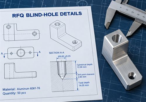
Example: An Aluminum Motorcycle Mounting Bracket
Imagine a motorcycle mounting bracket made from aluminum with a blind Ø8 mm hole.
The mating component requires 18 mm of usable cylindrical support.
The supplier plans to use a conventional drill with an approximately 118° point angle.
The approximate point height is:
0.30 × 8 mm = 2.4 mm
If the design also needs 2 mm of safety clearance below the mating component, the total drilled depth may need to be at least:
18 mm + 2.4 mm + 2 mm = 22.4 mm
The actual drawing should be finalized with the selected tool and required tolerance, but this calculation shows why a nominal “18 mm blind hole” may not provide enough total depth.
How to Reduce Blind-Hole Machining Cost
You can often reduce cost by making the functional requirement clear:
- Dimension full cylindrical depth separately from total depth.
- Avoid specifying a flat bottom unless it is necessary.
- Use a through hole if the assembly and appearance permit it.
- Increase the hole diameter if the function allows it.
- Avoid unnecessarily tight bottom-depth tolerances.
- Provide a section view for deep or threaded blind holes.
- Identify the mating screw, pin, bushing, or insert.
- Share annual quantity and repeat-order expectations.
- Ask the supplier to compare standard drilling, flat-bottom drilling, boring, and redesign options.
FAQ
Does a blind-hole depth include the drill point?
It depends on the drawing definition.
The drawing should state whether the dimension refers to full cylindrical depth, the drill-point apex, or total drilled depth.
How much clearance does a normal drill point need?
There is no single value.
It depends on the hole diameter and drill point angle. For an approximate 118° point, the conical height is about 0.30×D. For a 135° point, it is about 0.21×D.
Can a normal twist drill make a flat-bottom blind hole?
Normally, no.
A flat-bottom drill, counterboring, boring, or another finishing operation is usually required.
Is the drill-point depth the same for every drill?
No.
Drill point angle and tool geometry can change the conical depth. The actual tool drawing or supplier recommendation should be used for critical features.
How should threaded blind holes be dimensioned?
Specify:
- Thread size
- Usable full-thread depth
- Total tap-drill depth
- Bottom clearance
- Thread class, if relevant
- Inspection method
Can the supplier choose the drill point angle?
Often, yes.
If the functional requirements are clear, the supplier can recommend a tool and process. The drawing should focus on the finished hole requirements unless a specific tool is mandatory.
Final Takeaway
Blind holes should be dimensioned by separating the required cylindrical depth from the drill-point clearance and total drilled depth.
The drill-point clearance depends on:
- Hole diameter
- Point angle
- Tool geometry
- Material
- Drilling method
- Intended finishing process
A normal conical drill should not be treated as a flat-bottom tool.
For a reliable CNC machining quote, provide the hole diameter, usable cylindrical depth, total depth or bottom condition, material, tolerance, mating component, quantity, and inspection requirement.
If you are designing a blind hole for an aluminum, stainless steel, or carbon-steel component, send your 3D model and 2D drawing.
Our CNC machining team can review the drill-point clearance and recommend a practical production route for prototypes, small batches, OEM parts, and repeat production.
Have a blind-hole design that needs review? Send your drawing or 3D model for a manufacturing assessment and quotation.