Simulating CNC programs before machining uses specialized software to create a virtual replica of the entire machining process—including the CNC machine, cutting tools, workholding fixtures, and raw material—to verify G-code programs before any metal is cut. This digital validation detects collisions, confirms toolpaths, and identifies programming errors, transforming the manufacturing workflow from a risky “cut and hope” approach into a predictable, data-driven process that saves time, material, and money.
Introduction: Why Simulation Has Become Indispensable
For decades, proving out a new CNC program meant standing at the machine with a finger hovering over the feed hold button, watching nervously as the tool approached the workpiece for the first time. This “air cutting” approach—running the program with the tool slightly above the material—could catch some errors but could never reveal everything.
A single programming mistake can cost thousands of dollars: a destroyed spindle, a scrapped forging, a damaged fixture, or even operator injury. In industries like aerospace and medical device manufacturing, where parts can cost tens of thousands of dollars each and material lead times stretch for months, the risk of running an untested program is simply unacceptable .
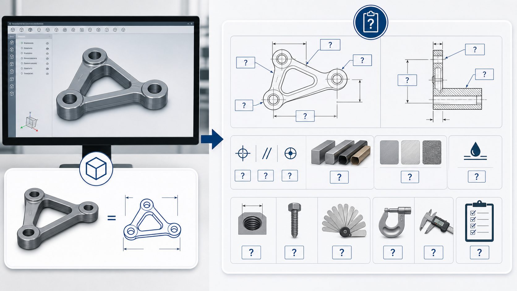
CNC program simulation addresses this risk head-on. By creating a complete digital twin of the machining process—including the machine tool, cutting tools, workpiece, and fixtures—simulation allows programmers to run G-code virtually, observing exactly what will happen on the shop floor before a single chip is produced .
The Core Purpose: Beyond Just “Seeing” the Cut
Many machinists new to simulation assume it’s merely a visualization tool—a way to watch a 3D animation of the tool moving through the part. While visualization is valuable, modern simulation software serves far more critical functions.
Collision Detection: The Life-Saving Feature
The most important function of CNC simulation is detecting collisions before they happen. A collision occurs when any part of the machine—the tool holder, the spindle head, the tool itself, or even the machine’s moving components—makes unintended contact with the workpiece, fixtures, or other parts of the machine.
A high-fidelity simulation includes the complete machine geometry: the spindle head, the tool holder (not just the cutting tool), the workholding fixtures, vises, clamps, and even the machine’s enclosure . When the simulation runs, the software checks every moving component against every static component, flagging any interference.
For five-axis machining, this collision detection becomes absolutely essential. The complex simultaneous motion of rotary axes makes it virtually impossible for even experienced programmers to visualize every potential collision point. As one aerospace machinist noted, “Even experienced programmers cannot fully predict the actual motion of the machine.”
Verification of Motion and Material Removal
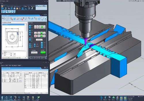
Beyond collision detection, simulation verifies that the machine moves exactly as intended. The toolpath should stay within the bounds of the workpiece, never cutting air unnecessarily. Material should be removed layer by layer, revealing the final part geometry without undercuts or uncut regions.
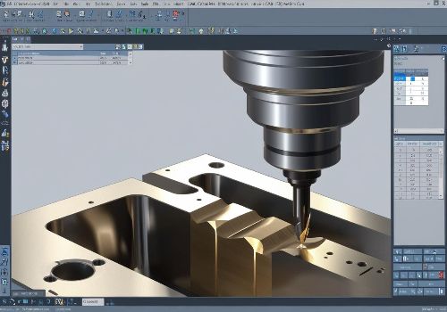
Modern simulation software displays stock removal visually, showing material gradually disappearing as the virtual tool moves through it . This visual feedback is invaluable for catching programming errors—a tool that misses a feature completely or cuts too deeply becomes immediately obvious.
Cycle Time Estimation
Simulation software calculates the exact time the program will take to run, based on the programmed feed rates and the machine’s acceleration/deceleration characteristics. This allows production planners to schedule accurately and helps identify whether a program’s cycle time is competitive.

Types of Simulation: From Basic to Advanced
Not all simulation is created equal. The level of detail and accuracy varies significantly between approaches.
CAM-Based Toolpath Simulation (Basic)
Most CAM software includes basic simulation that shows the toolpath relative to the workpiece model. This “toolpath verification” is useful for visualizing the cut but has significant limitations: it shows the toolpath geometry but doesn’t know the actual geometry of the tool holder, the spindle, or the machine’s moving parts.
G-Code Driven Simulation (Intermediate)
A significant step up from CAM-based simulation is simulation driven directly by the G-code that will run on the machine. Running the exact G-code—not a CAM-generated approximation—ensures that the simulation reflects what the machine will actually do .
G-code driven simulation reveals errors that CAM simulation would miss: incorrect post-processor settings, machine-specific code that the CAM system doesn’t generate, or subtle motion differences between the CAM’s simulation and the actual machine’s behavior.
Machine Simulation with Virtual CNC (Advanced)
The most sophisticated level of simulation integrates a virtual version of the actual CNC control—the same software kernel that runs on the physical machine. Siemens refers to this as VNCK (Virtual NC Kernel) .
With VNCK, the simulation environment includes:
-
The exact CNC control logic and parameter settings
-
The same acceleration and deceleration characteristics
-
Machine-specific behaviors and limitations
-
Tool change sequences and auxiliary functions
When you run a program on a virtual CNC, the behavior precisely mirrors what would happen on the physical machine, right down to how the control handles G-code syntax variations.
Table: Comparison of Simulation Types
| Simulation Type | What It Shows | Limitations | Best For |
|---|---|---|---|
| CAM Toolpath (CL Data) | Tool center point movement, material removal | Ignores holder, spindle, and machine geometry; CL data may differ from final G-code | Quick visual check during programming |
| G-Code Simulation | Actual G-code execution, basic tool/holder collision | May not include complete machine kinematics or control behavior | Most production environments |
| Virtual CNC Simulation (VNCK) | Complete machine behavior with actual control logic | Requires significant setup and computing resources | High-risk, high-value parts (aerospace, medical, defense) |
The Modern Simulation Workflow
The integration of simulation into the CAM workflow has become increasingly seamless, with software vendors building simulation capabilities directly into their CAM platforms rather than requiring separate, standalone simulation products.
Step 1: Model the Complete Machining Environment
Before any programming begins, the digital environment must be populated with accurate models of every physical component that will interact during machining:
-
The machine tool itself, including the base, columns, spindle head, and any rotary axes
-
The tooling assembly, including the tool holder, collet nut, and the cutting tool itself
-
Workholding devices, including vises, clamps, fixture plates, and locating pins
-
The raw stock material, modeled to actual dimensions
-
Any additional components, such as tailstocks, steady rests, or robot loaders
Machine simulation platforms can map the entire machine tool, supporting a variety of manufacturers’ equipment and allowing shops to build verification environments that match their specific equipment.
Step 2: Generate and Post-Process Toolpaths
Using the CAM software, programmers create toolpaths based on the part geometry and the machining strategy. Once toolpaths are complete, the post-processor translates them into G-code specific to the target machine tool and CNC control.
Step 3: Simulate Using the Actual G-Code
The critical step is running the simulation using the actual G-code that will be loaded onto the machine, not the CAM’s internal toolpath data . This catches errors introduced by the post-processor—a notoriously common source of problems.
Step 4: Analyze Results and Iterate
As the simulation runs, the software continuously checks for:
-
Collisions between any moving and stationary components
-
Rapid moves that could crash into fixtures or the part
-
Violations of machine limits (travel, speed, acceleration)
-
Unmachined features or excessive stock remaining
-
Toolpath inefficiencies or unnecessary air cutting
When issues are detected, programmers return to the CAM system, adjust the toolpaths or parameters, regenerate the G-code, and simulate again. This iterative process continues until the simulation shows a clean, error-free machining process.
Step 5: Confidence to Cut
Only when the simulation confirms that the program runs safely and correctly does the program move to the machine tool. The time invested in simulation pays for itself many times over by eliminating the “prove-out” time on the machine—and the risk of catastrophic crashes.

Technology Driving Simulation Forward
GPU Acceleration for Real-Time Simulation
One of the most significant recent advances in CNC simulation is the use of Graphics Processing Units (GPUs) to accelerate simulation calculations . Traditional CPU-based simulation could be slow, especially for complex five-axis programs with continuous material removal visualization.
GPU acceleration dramatically speeds up stock updates and collision detection, making simulation feel nearly real-time even for complex machining scenarios. The system can automatically fall back to CPU processing when needed, ensuring stable and predictable operation across different use cases.
Integration with Digital Twins
The concept of the “digital twin”—a complete virtual replica of a physical system—has transformed simulation from a standalone verification tool into a central element of the manufacturing workflow.
When the CAM system, the simulation platform, the post-processor, and the machine tool are all connected through a common digital thread, design changes propagate automatically. If an engineer modifies the CAD model, the CAM toolpaths update, the simulation runs automatically, and the post-processor generates new G-code—all without manual intervention.
Cloud-Based Simulation and Post-Processing
Siemens’ Post Hub, for example, provides a cloud-based library of post-processors and machine kits, offering CNC machine data, tooling, and controller settings to generate validated, production-ready NC programs . This cloud-based approach ensures that the post-processor used in simulation exactly matches the one that will generate the final G-code.
Similarly, Next Generation Shop Floor Programming (NGSP) is now available as a web-based application, simplifying deployment across CNC controllers, mobile devices, and desktop systems.
Real-World Case Study: Aerospace Component Manufacturer
The German Aerospace Center’s (DLR) Institute of Robotics and Mechatronics provides a compelling example of simulation’s value . The institute manufactures complex robotic components with lightweight structures—parts where material removal often exceeds 90% of the original stock.
Before implementing advanced simulation, the team used five-axis machining only when absolutely necessary because programming was too time-consuming and they lacked reliable G-code simulation to verify programs safely.
After adopting hyperMILL’s VIRTUAL Machining simulation technology, the situation transformed completely. The team now generates optimized five-axis NC programs in a fraction of the previous time, and the G-code simulation provides near-100% reliability in detecting collisions before machining begins.
As one of the institute’s precision machinists noted, “The investment in VIRTUAL Machining and BEST FIT has absolutely paid off. Not only has our programming efficiency significantly improved, but we also have NC code simulation with the highest level of safety.”
Simulation for Different Machine Configurations
Three-Axis Machining
For three-axis work, simulation is valuable but less critical than for multi-axis. The constrained motion makes collisions easier for programmers to visualize, and the primary value comes from detecting holder-to-fixture interferences and verifying material removal.
Four- and Five-Axis Machining
For four- and five-axis work, simulation is not optional—it is essential. The simultaneous motion of rotary axes creates complex tool trajectories that no human can reliably visualize. Only simulation can reveal:
-
Whether the tool holder will clear the part at extreme tilt angles
-
Whether the machine’s rotary limits will be exceeded
-
Whether the tool will collide with fixtures as the table rotates
-
Whether the programmed tool orientation is physically achievable
Mill-Turn and Multi-Tasking Machines
The most complex simulation requirements come from mill-turn machines that combine turning and milling operations, often with multiple turrets, spindles, and tools operating simultaneously. Simulation for these machines must coordinate multiple channels of code, verifying that tools from different turrets don’t collide and that synchronized operations proceed safely.
Conclusion: Simulation as a Competitive Necessity
The question is no longer whether to simulate CNC programs before machining, but rather how comprehensively to simulate. As machines become more complex, parts more valuable, and delivery timelines tighter, the risk of running an untested program has become unacceptable.
For shops producing aerospace components with tight tolerances, medical devices with expensive raw materials, or any high-value parts, simulation has moved from “nice to have” to “competitive necessity.”
The good news is that simulation technology has never been more accessible. Integrated CAM simulation, GPU-accelerated verification, and cloud-based post-processing have lowered the barriers to entry. For shops just beginning their simulation journey, starting with basic G-code simulation is a practical first step—one that pays for itself with the first collision it prevents.
Ready to bring simulation to your CNC workflow? Contact our applications engineering team to discuss simulation solutions tailored to your machine tools and part complexity.