Quick Answer
External corner radii should be designed to remove sharp exposed edges, reduce stress concentration, improve tool access, support safer handling, and match the part’s functional requirements. The correct radius depends on the material, part size, machining method, available tooling, assembly conditions, and whether the edge is structural, cosmetic, or used for handling.
There is no single radius that works for every CNC component. A good design uses larger radii where strength and safety matter, smaller controlled radii where clearance is limited, and clearly defined edge requirements on the drawing.
Why External Corner Radii Matter in CNC Part Design
An external corner is the outside edge where two or more surfaces meet. If the edge is left sharp, it may create several problems:
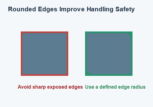
- Increased risk of cuts during handling or assembly
- Higher local stress under impact or vibration
- Difficult deburring requirements
- Poor surface consistency after machining
- Greater risk of edge damage during transport
- Unclear expectations between the buyer and supplier
For CNC machined aluminum brackets, stainless steel housings, motorcycle mounting parts, spacers, adapters, and protective components, edge design affects both safety and manufacturability.
A defined external radius also makes the part easier to inspect. Instead of relying on a general “break sharp edges” instruction, the manufacturer can produce and measure a specific feature.
1. Remove Sharp Edges That Will Be Handled Frequently
The first design question should be simple:
Will a person touch, install, adjust, package, or service this edge?
If the answer is yes, a sharp external corner should normally be avoided.
This is particularly important for:
- Motorcycle brackets
- Handlebar clamps
- Foot peg components
- Battery boxes
- Sheet metal covers
- Engine guards
- Mounting plates
- Service tools
- Enclosures and access panels
A small radius or controlled chamfer can make a large difference during assembly. It reduces the chance of cuts, makes the part more comfortable to handle, and helps prevent damage to gloves, cables, wiring, seals, and nearby components.
For parts that will be installed manually, specify the required edge condition instead of leaving it entirely to the manufacturer.
2. Use Larger Radii in High-Stress Areas
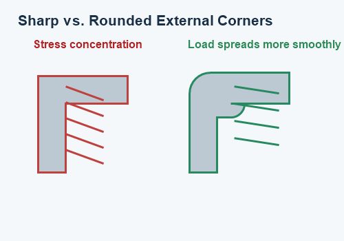
Sharp corners can increase stress concentration because the load changes direction abruptly at the corner. A radius creates a smoother transition between surfaces and helps distribute the load over a larger area.
Larger external radii are often useful near:
- Bolt holes
- Mounting bosses
- Bracket bends
- Load-bearing arms
- Suspension-related components
- Vibration-exposed parts
- Thin sections connecting to thicker sections
- Areas exposed to repeated impact
This does not mean every corner should be made as large as possible. A large radius can interfere with mating parts, reduce clearance, or change the appearance of the product.
The correct approach is to identify the load path first. Use larger radii where the component experiences bending, vibration, impact, or repeated tightening. Use smaller radii where packaging and clearance are more important.
3. Match the Radius to CNC Tool Access
The radius should also be practical for the selected machining process.
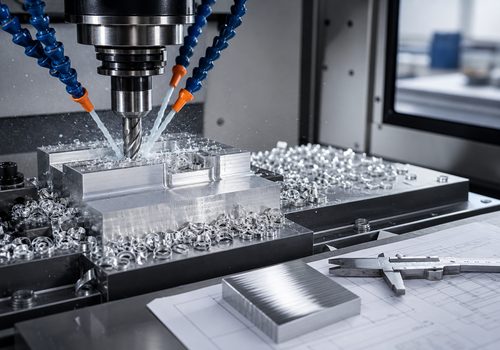
For CNC milling, the supplier must consider:
- Tool diameter
- Tool reach
- Part orientation
- Workholding method
- Number of setups
- Cutting access around the corner
- Required surface finish
- Material being machined
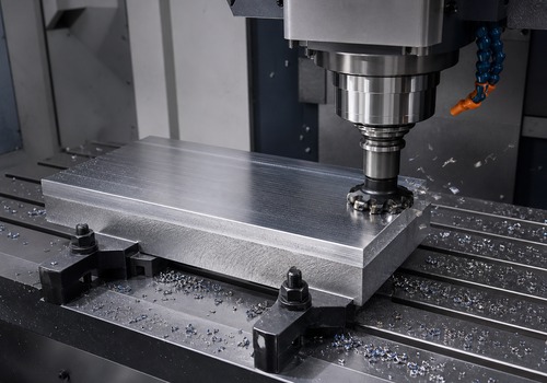
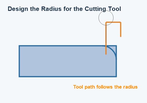
External profiles are often easier to machine than internal corners because the cutter can follow the outside contour. However, the radius still affects toolpath length, machine motion, fixture clearance, and edge quality.
Very small radii may require a small tool, which can increase machining time and tool wear. Very large radii may require additional contouring or affect how the part is positioned in the fixture.
For this reason, the radius should be reviewed together with the entire geometry rather than treated as an isolated drawing detail.
4. Avoid Using a Radius That Creates Assembly Problems
A radius improves safety and stress distribution, but it also removes material from the corner. This can affect mating parts.
Before adding a large radius, check:
- Whether another component sits tightly against the edge
- Whether a gasket or seal needs a flat contact area
- Whether a washer requires a full seating surface
- Whether the part locates against a sharp reference corner
- Whether an adjacent bracket needs full contact
- Whether the radius interferes with a cable, hose, or fastener
For example, a large radius on a mounting plate may prevent a washer from sitting correctly. A radius near a gasket surface may create a leakage path. A radius near a locating shoulder may reduce assembly accuracy.
The best design usually combines a larger radius on exposed or stressed edges with a controlled edge break near functional contact surfaces.
5. Separate Functional Radii from General Edge Breaks
A common drawing problem is using one general note for every edge. A statement such as “deburr all edges” may not define the actual geometry clearly enough.
A better drawing distinguishes between:
- Critical external radii
- General edge breaks
- Cosmetic edge treatment
- Safety-related edges
- Mating or sealing edges
- Edges that must remain sharp for positioning
For example, a drawing may specify a defined radius on a load-bearing bracket corner while using a general chamfer or edge-break note for non-critical edges.
This prevents suppliers from interpreting every corner in the same way. It also makes inspection more efficient because the manufacturer knows which features require special attention.
6. Consider Material Behavior
Different materials respond differently to corner geometry and machining forces.
For aluminum CNC parts, a radius can help reduce edge damage and improve handling. Aluminum is relatively soft, so sharp thin edges may be easier to dent or deform during fixturing and transport.
For stainless steel parts, larger radii may help reduce stress concentration, but machining time and tool wear should also be considered.
For carbon steel components, the radius may be influenced by loading, coating, welding, and corrosion-protection requirements.
For engineering plastics such as Delrin, PEEK, or nylon, corner geometry can affect deformation, stress relaxation, and long-term dimensional stability.
The drawing should therefore identify the material and application. A radius that works well for a decorative aluminum cover may not be appropriate for a highly loaded stainless steel mounting bracket.
7. Use Radii to Improve Coating and Finishing Results
External corner geometry also influences surface finishing.
Sharp edges can create problems during:
- Anodizing
- Powder coating
- Painting
- Plating
- Brushing
- Polishing
- Deburring
- Protective film application
Sharp edges may receive less consistent coating coverage or become damaged during handling. A controlled radius can make the finished surface more uniform and reduce the chance of exposed edges.
For anodized aluminum parts, powder-coated brackets, and polished motorcycle components, the final appearance can be improved when the edge design is consistent across the part.
If the corner radius is visually important, include it as a defined feature instead of relying only on a surface-finish note.
8. Design the Radius for Safer Packaging and Transport
CNC parts are often packaged together with separators, protective films, foam, or bags. Sharp external edges can cut packaging materials or scratch adjacent components.
This is a concern for:
- Small production batches
- Export shipments
- High-value machined parts
- Finished anodized parts
- Polished components
- Kits containing multiple metal parts
A small radius can reduce contact damage during transportation. It also makes it easier to use protective packaging without creating excessive packaging cost.
For parts shipped internationally, the buyer should communicate whether the supplier needs to use individual wrapping, edge protectors, foam inserts, or custom trays.
9. Do Not Apply the Same Radius Everywhere
A uniform radius may look visually consistent, but it is not always the best engineering decision.
Different edges may have different requirements:
| Edge Type | Recommended Design Focus |
|---|---|
| Handled external edge | Prioritize safety and comfort |
| Load-bearing corner | Prioritize stress reduction |
| Mating edge | Protect clearance and contact |
| Sealing edge | Maintain a flat and controlled surface |
| Cosmetic edge | Match appearance and finishing |
| Tool-access edge | Match cutter and setup limitations |
| Reference edge | Preserve locating accuracy |
The goal is not to make every corner identical. The goal is to give every corner the geometry it needs.
10. Define Radius Requirements Clearly on the Drawing
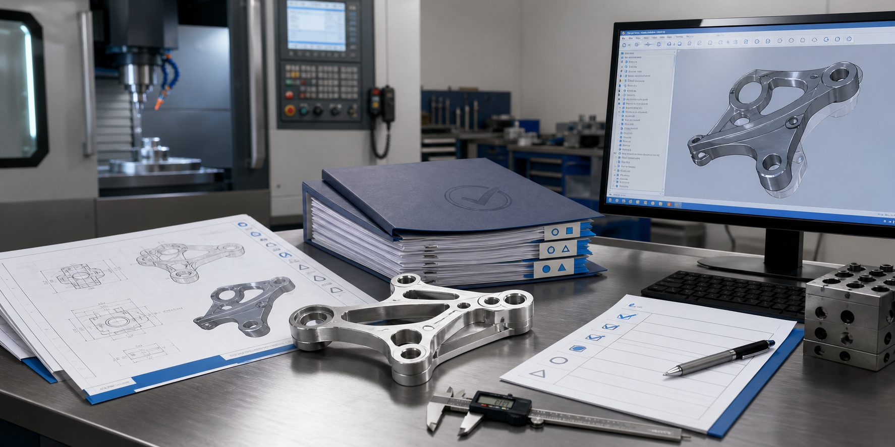
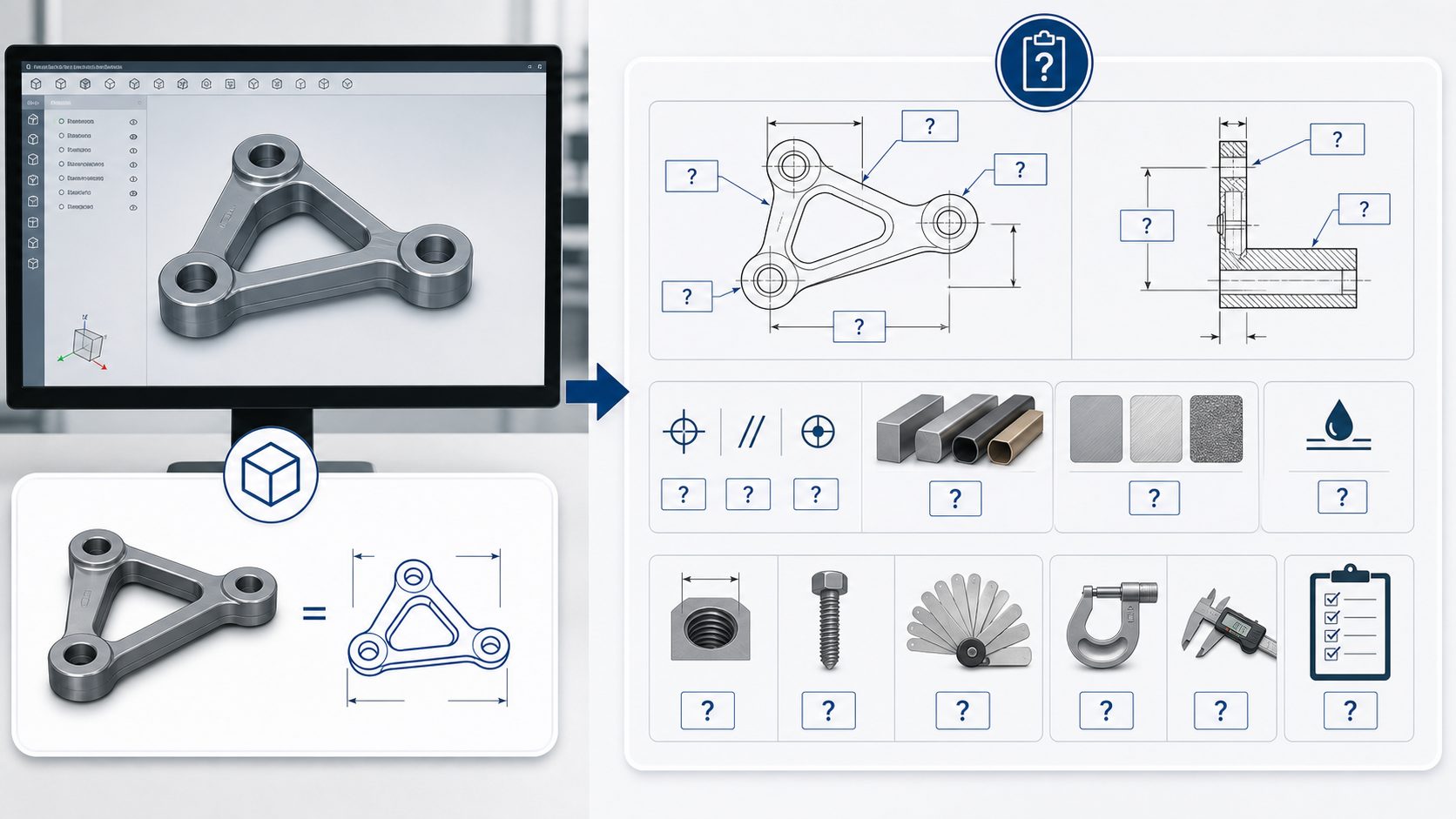
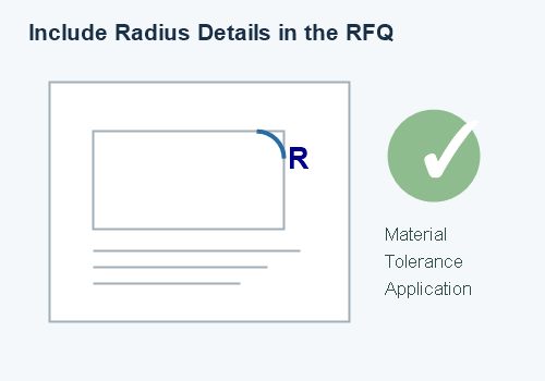
A 3D model may show a rounded shape, but it may not communicate the exact radius or its importance. A 2D drawing should be used to clarify critical edge details.
Include:
- Radius value
- Tolerance if required
- Location of the radius
- Whether the feature is functional or cosmetic
- General edge-break requirement
- Surface-finish requirement
- Datum reference if inspection depends on a specific surface
- Section view for complex corners
A drawing should also clarify whether the radius is measured before or after coating or finishing if the final process may change the edge profile.
What Radius Should You Specify?
There is no universal external corner radius for all CNC parts. The correct value depends on:
- Part thickness
- Material
- Load and vibration
- Available clearance
- Tool access
- Product appearance
- Assembly method
- Surface treatment
- Inspection requirements
- Expected production quantity
As a practical starting point:
- Use a small controlled radius or chamfer for general handling edges.
- Use a larger radius for corners exposed to impact or bending.
- Use generous transitions near heavily loaded features.
- Use smaller radii near tight mating areas.
- Confirm the design with the CNC supplier before final release.
Do not select a radius only because it looks attractive in CAD. It should also be practical to machine, inspect, finish, package, and assemble.
RFQ Information for CNC Parts with External Radii
When requesting a quote for a CNC machined part with important corner radii, provide:
- 3D CAD model
- 2D manufacturing drawing
- Material and material grade
- Quantity
- Critical radius dimensions
- General edge-break requirements
- Tolerance requirements
- Surface finish
- Coating or anodizing requirements
- Application and expected load
- Assembly or mating-part information
- Packaging requirements
- Prototype or production quantity
If only a 3D model is provided, a supplier may not know which radii are critical. This can result in different interpretations, price changes, or a sample that does not match the intended function.
Example: Motorcycle Mounting Bracket
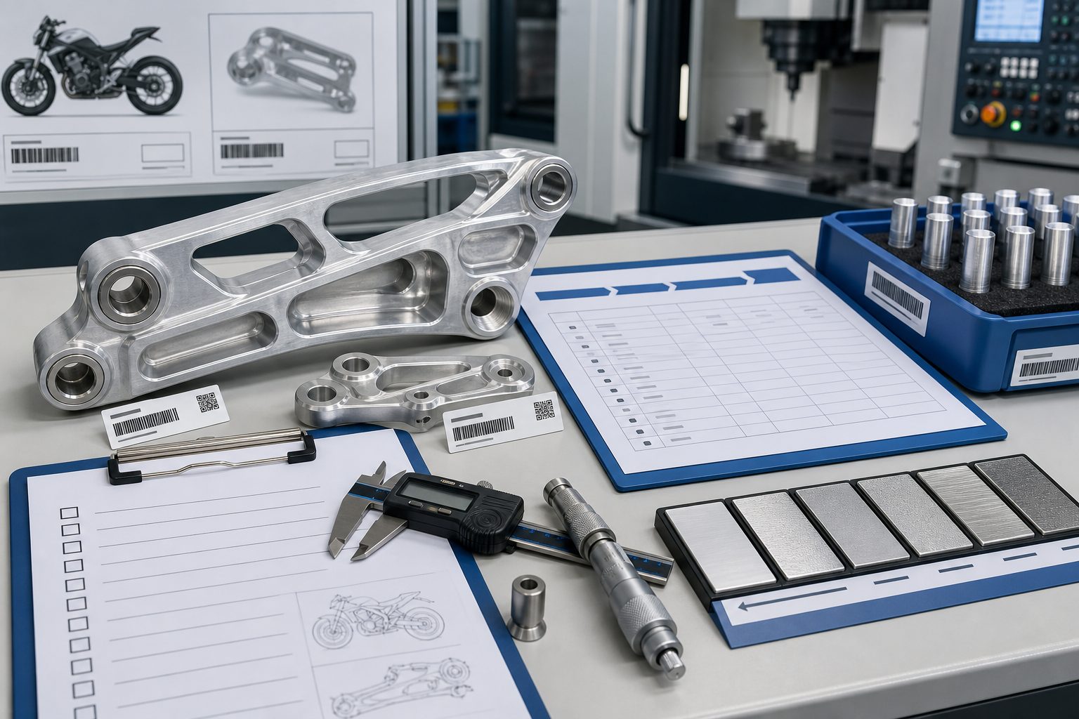
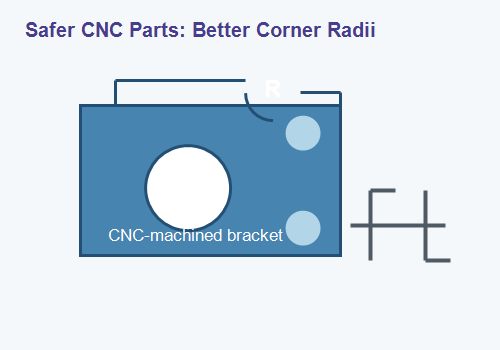
Consider a CNC machined motorcycle mounting bracket with two bolt holes, a central pocket, and an external arm.
A practical design could include:
- Larger radii at the transition between the arm and mounting body
- Smaller edge breaks around bolt-hole openings
- A controlled radius on exposed hand-accessible corners
- Flat seating surfaces around washers
- Clear dimensions for the central pocket
- A general deburring instruction for non-critical edges
This approach protects the load-bearing area while preserving assembly clearance. It also gives the manufacturer enough information to choose suitable tools and inspection methods.
How a CNC Supplier Can Help
A capable CNC machining supplier can review external radii during the quotation stage and identify potential issues before production starts.
A design-for-manufacturing review may check:
- Whether the radius is easy to machine
- Whether the tool can reach the area
- Whether the radius conflicts with assembly
- Whether the corner needs a tighter tolerance
- Whether the radius should be changed for finishing
- Whether the geometry requires another setup
- Whether the edge can be inspected reliably
Early feedback is especially useful for prototypes, small batches, and custom motorcycle parts where the design may still be changing.
FAQ
Why are external corner radii important in CNC parts?
External corner radii improve handling safety, reduce sharp edges, help distribute stress, protect coatings, and reduce the risk of edge damage during machining and transport.
Should every CNC part have rounded external corners?
Not every corner needs the same radius. Functional edges, mating surfaces, reference edges, and cosmetic edges may require different treatments.
Are larger radii always better?
No. A large radius may interfere with assembly, reduce contact area, affect clearance, or change the product appearance. The radius should match the functional requirement.
What is the difference between a radius and a chamfer?
A radius creates a curved transition, while a chamfer creates a flat angled transition. Both can reduce sharp edges, but their structural, visual, and machining effects are different.
Can external corner radii increase CNC machining cost?
They can affect machining time, tool selection, setups, and inspection. However, a well-designed radius can also reduce deburring, improve safety, and prevent later quality problems.
Should I show corner radii in the 3D model?
Yes, but critical radii should also be dimensioned on the 2D drawing. The drawing should explain which edge details are mandatory.
Conclusion
External corner radii should be designed according to safety, load, assembly, machining access, finishing, and inspection requirements. A good radius removes unnecessary sharp edges without creating new clearance or manufacturing problems.
For most CNC parts, the most effective approach is to:
- Use larger radii in high-stress areas
- Protect edges that will be handled frequently
- Match the radius to available tooling
- Preserve flat mating and sealing surfaces
- Separate critical radii from general edge breaks
- Define important radii clearly on the drawing
- Review the design with the CNC supplier before production
If you are developing a custom CNC machined bracket, mounting plate, adapter, enclosure, or motorcycle metal part, send us your 3D model, 2D drawing, material requirement, quantity, and application details. We can review the external corner radii for manufacturability and prepare a practical quotation for prototypes, small batches, or repeat production.