Optimizing CNC code for faster machining involves systematically reducing non-cutting time (rapid moves, tool changes, positioning) while maximizing in-cut efficiency through optimized toolpaths, appropriate cutting parameters, and intelligent program structure. The most effective optimizations reduce cycle time by 15-40% without changing tools, machines, or material—simply by making the existing process run more efficiently.
Introduction: The Hidden Time in Every Program
Walk onto any shop floor and watch a CNC machine run. For every minute the spindle is cutting material, how many seconds is the machine rapid-traversing between features? How much time is spent waiting for tool changes? How many moves are there that accomplish nothing but moving air?
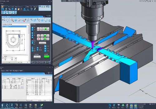
The typical CNC program is full of inefficiencies—not because programmers are careless, but because generating efficient code manually is tedious and time-consuming. Modern CAM systems generate safe, reliable code by default. But “safe and reliable” is not the same as “fast.”
The gap between default CAM output and fully optimized code is often 20-40% of the total cycle time. Bridging that gap requires understanding where time is lost and systematically applying proven optimization techniques.
This guide focuses on optimizations that are free—they cost no additional tooling, no machine upgrades, no material changes. They simply require better programming.
The Two Frontiers of Optimization
Cycle time optimization operates on two distinct frontiers:
-
In-Cut Efficiency: Making the machining itself faster through optimized toolpaths, better cutting parameters, and efficient strategies
-
Non-Cutting Efficiency: Eliminating wasted motion, reducing tool changes, and streamlining program flow
Both matter. A program with perfect in-cut efficiency but excessive rapids and tool changes will still be slow. A program with lightning-fast rapids but inefficient cutting parameters will still be slow. The best programs optimize both.
Part 1: Optimizing Non-Cutting Time
Non-cutting time includes everything the machine does when the tool is not engaged with material: rapid traverse moves, positioning moves, tool changes, coolant on/off, and program termination sequences.
1.1 Reduce Rapid Move Distances
The most obvious inefficiency in many programs is long rapid moves that traverse unnecessarily large distances.
The Problem: CAM systems often return tools to a safe retract plane (e.g., Z1.0) between every feature, even when features are close together.
The Optimization: Use incremental retracts—lifting the tool just enough to clear the next feature rather than returning to a global clearance plane.
Example:
(Unoptimized - returns to Z1.0 between holes)
G00 Z1.0
G00 X1.0 Y1.0
G81 Z-0.5 R0.1 F10.0
G00 Z1.0
G00 X2.0 Y1.0
G81 Z-0.5 R0.1 F10.0

(Optimized - retracts only to clearance for next feature)
G00 X1.0 Y1.0
G81 Z-0.5 R0.1 F10.0
G00 X2.0 Y1.0   (Position moves at retract plane, no extra Z move)
G81 Z-0.5 R0.1 F10.0
Potential Savings: On parts with many features, reducing rapid distance can save seconds to minutes per cycle.
1.2 Optimize Approach and Departure Strategies
CAM systems often generate conservative approach and departure moves—long lead-in and lead-out lines that guarantee clearance but waste motion.
The Optimization: Shorten lead-in/lead-out distances where clearance permits. For pocketing operations, use helical ramps that enter the cut while cutting rather than positioning moves that waste time.
Potential Savings: 1-3 seconds per operation; on a 50-operation program, minutes per cycle.
1.3 Minimize Tool Changes
Every tool change costs time. A typical automatic tool change takes 5-15 seconds. Ten unnecessary tool changes add a minute or more to cycle time.
The Optimization: Reorder operations to group all work that can be done with the same tool before changing. If a single tool can rough and finish a feature, do both before changing tools rather than roughing all features with one tool, then finishing all features with another.
The Trade-off: Grouping operations by tool may require longer rapids between features. The net benefit depends on the specific geometry.
Rule of Thumb: If the time saved by eliminating a tool change exceeds the additional rapid time required to reach grouped features, the optimization pays off.
1.4 Eliminate Unnecessary Coolant and Auxiliary Commands
Every M08 (coolant on) and M09 (coolant off) takes time to execute, as do spindle start/stop commands.
The Optimization: Keep coolant on between operations when possible rather than turning it off and on for every feature. For multi-operation programs, turn coolant on at the beginning of the tool’s work and off at the end.
Potential Savings: Fractions of a second per command—but fractions add up across hundreds of commands.
1.5 Optimize Retract Planes
CAM systems default to safe retract planes that clear the tallest feature on the entire part, even when the current operation is nowhere near that height.
The Optimization: Set operation-specific retract planes just high enough to clear local features. Use incremental retracts (G91) rather than absolute (G90) when appropriate.
Caution: This optimization increases risk. Thorough simulation is essential.

Part 2: Optimizing Cutting Parameters
Cutting parameters—spindle speed, feed rate, depth of cut—directly affect how quickly material is removed. The default parameters in CAM libraries tend toward conservative, safe values rather than high-productivity values.
2.1 Increase Feed Rates Within Tool Capability
The most direct way to reduce cycle time is to increase feed rate. Most CAM default feeds are significantly lower than what the tool can actually handle.
The Method: Test increasing feed rates incrementally (10-20%) on an existing program. Monitor tool wear, surface finish, and machine load. Push until one of these factors reaches an acceptable limit.
Typical Gains: 10-30% reduction in cut time is often achievable without changing tooling.
2.2 Optimize Depth of Cut and Stepover
Depth of cut and stepover determine material removal rate. The interaction between these parameters is complex—increasing one may require decreasing the other.
For Roughing: Maximize depth of cut first, then set stepover to balance tool load. For many materials, axial depths of 1-2 times tool diameter are achievable.
For Finishing: Light stepover (5-10% of tool diameter) with full axial depth maximizes productivity while maintaining surface finish.
2.3 Use High-Efficiency Machining (HEM) Toolpaths
Standard toolpaths vary tool engagement constantly, creating force spikes that limit productivity. HEM toolpaths maintain constant engagement, allowing significantly higher material removal rates with the same tools.
The Strategy: High axial depth (full tool length) with low radial engagement (5-10% of tool diameter). The tool stays continuously engaged, cutting forces remain low and consistent, and material removal rates can be 2-4 times higher than conventional roughing.
CAM Requirements: HEM requires CAM software with adaptive or dynamic toolpath capabilities—most modern CAM packages support this.
2.4 Match Feed Rates to Material Conditions
Different material conditions require different cutting parameters. A single feed rate across an entire operation is rarely optimal.
The Optimization: Program higher feed rates for straight, open cuts and lower feed rates for corners, tight spaces, or heavy engagement areas. Many modern CAM systems can automatically adjust feed rates based on tool engagement.
2.5 Use Plunge Milling for Deep Cavities
For deep cavities, traditional side milling forces long tools that deflect and cut inefficiently. Plunge milling (machining with the end of the tool, moving vertically) uses shorter, stiffer tools and can be significantly faster.
When to Use: Cavities deeper than 4 times tool diameter, hard materials, or any situation where tool deflection limits productivity.
Part 3: Optimizing Toolpath Strategy
The path the tool follows through the material profoundly affects cycle time. Different strategies for the same feature can vary in time by 2-5x.
3.1 Replace Zig-Zag with One-Way Cutting When Appropriate
Zig-zag toolpaths cut in alternating directions, with a rapid traverse between passes. One-way toolpaths cut in a single direction, with a longer rapid return between passes.
Counterintuitive Truth: Despite the longer rapid move, one-way cutting can be faster because it maintains climb milling conditions throughout, allowing higher feed rates. Zig-zag alternates between climb and conventional, forcing conservative feeds.
3.2 Use Trochoidal Milling for Slotting
Traditional slotting (plunging to full depth then moving straight) generates extremely high cutting forces, forcing slow feeds and shallow depths. Trochoidal milling moves the tool in a circular, looping path while advancing slowly along the slot.
The Benefit: Constant, low engagement allows much higher axial depths and feed rates. A slot that takes 2 minutes with conventional slotting might take 20 seconds with trochoidal milling.
3.3 Optimize Lead-In/Lead-Out Strategies
The tool must enter and exit the material smoothly. The choice of lead-in strategy affects cycle time.
-
Helical ramping: Efficient for entering pockets; the tool cuts while entering
-
Zig-zag ramping: Slower than helical; may be necessary for some materials
-
Plunge entry: Fastest entry but hardest on tools; use only when appropriate
3.4 Rest Machining: Don’t Cut Air
Rest machining identifies areas where material remains after roughing and creates toolpaths that cut only those areas.
The Benefit: Rather than re-cutting the entire surface with a smaller tool, rest machining cuts only where material remains, saving significant time on complex parts.
Part 4: Programming Structure and Control Settings
4.1 Use G00 (Rapid) Appropriately
G00 rapid moves are maximum speed but not necessarily straight line. Different controls handle G00 differently; some move axes independently, creating dog-leg paths that may not be safe for internal moves.
The Optimization: For long, unobstructed moves, G00 is fastest. For moves near fixtures or part features, use G01 with high feed rates for predictable, straight-line motion.
4.2 Minimize G04 (Dwell) Time
Dwell commands are often inserted by CAM systems “to be safe.” Many are unnecessary.
The Method: Review the program for G04 commands. Test removing them one at a time. If the machine operates correctly without the dwell, leave it out.
4.3 Optimize Acceleration/Deceleration Parameters
Machine parameters control how quickly axes accelerate and decelerate. Conservative settings limit productivity.
The Optimization: Work with your machine tool builder or service provider to adjust acceleration parameters for your typical work. Higher acceleration settings reduce the time spent ramping up to and down from feed rates.
Warning: Parameter changes affect all programs and can increase wear on mechanical components. Professional guidance is recommended.
4.4 Use High-Speed Machining (HSM) Modes
Many modern controls have HSM modes that optimize motion for high feed rates. These modes smooth cornering, reduce vibration, and maintain higher average feed rates through complex toolpaths.
The Action: Enable HSM mode if your control supports it. The difference in cycle time can be 10-20% on complex three-axis work and even more on five-axis.
Part 5: Workflow and Process Optimizations
5.1 Standardize Tool Libraries
CAM systems allow tool libraries with pre-defined speeds and feeds for specific materials and operations. A well-built library eliminates the need to calculate parameters for each program.
The Benefit: Consistent, optimized parameters across all programs; faster programming; fewer errors.
5.2 Use Templates and Macros
For recurring features—bolt circles, pockets, bosses—create macros or CAM templates that automatically apply optimized toolpaths and parameters.
The Benefit: One-time optimization effort applies to every future use of that feature.
5.3 Post-Processor Optimization
The post-processor translates CAM toolpaths into G-code. Off-the-shelf post-processors are safe but rarely optimal.
The Opportunity: Customizing the post-processor to generate more efficient code—shorter rapids, fewer unnecessary moves, optimized block structure—multiplies the benefit across every program.
Case Study: 30% Cycle Time Reduction Without New Tooling
The Part: Aluminum aerospace bracket, 100 pieces per month
Baseline Program (CAM default):
-
Cycle time: 24 minutes
-
12 tool changes
-
Conservative feeds: 40 IPM roughing, 20 IPM finishing
-
Standard toolpaths (zig-zag roughing, contour finishing)
Optimizations Applied:
-
Converted roughing to HEM toolpaths (adaptive clearing)
-
Increased feed rates to 120 IPM roughing, 60 IPM finishing
-
Grouped operations to reduce tool changes from 12 to 7
-
Shortened rapid moves between features
-
Enabled HSM mode on control
Results:
-
New cycle time: 16.5 minutes (31% reduction)
-
No tooling changes, no machine upgrades, no additional cost
-
Surface finish improved (HEM produces smoother cuts)
-
Tool life unchanged (reduced cutting forces offset higher speeds)
The Iterative Optimization Process
Optimization is not a one-time event; it is an ongoing process of measurement, adjustment, and validation.
Step 1: Establish Baseline
Run the program as-is. Measure actual cycle time with a stopwatch. Note which operations take the longest.
Step 2: Identify High-Impact Opportunities
Look for:
-
Long, straight cuts that could run faster
-
Deep pockets that could use HEM or plunge milling
-
Frequent tool changes that could be grouped
-
Excessive rapid moves between features
Step 3: Apply One Change at a Time
Change one variable—feed rate, toolpath strategy, operation order—and test. Measure the effect. If positive, keep it. If negative or neutral, revert.
Step 4: Validate and Document
After optimizing, run the program multiple times to ensure consistency. Document the optimized parameters for future programs on similar parts.
Conclusion: The Optimization Mindset
Optimizing CNC code for faster machining is not about dramatic breakthroughs; it is about disciplined, incremental improvement. Every second saved on every cycle multiplies across every part produced. A 10% cycle time reduction on a 10-minute part run 1,000 times saves nearly 17 hours of machine time.
The most successful shops embed optimization into their programming workflow. They don’t just generate code; they refine it. They measure cycle times, track improvements, and share successful strategies across programming teams.
The tools and techniques described here require no capital investment—only attention, discipline, and a commitment to continuous improvement. In a competitive industry where every minute matters, optimization is not optional. It is essential.
Ready to optimize your CNC programs? Contact our applications engineering team for a free cycle time analysis of one of your existing programs.