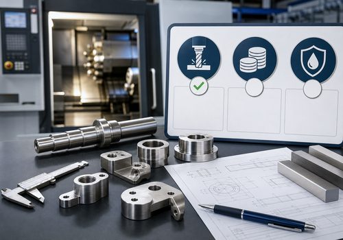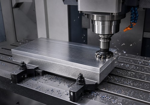
Grain direction affects a wrought aluminum part more strongly through mechanical properties, residual stress, distortion, crack resistance, burr behavior, and final part orientation than through cutting direction alone. For simple, thick components, its effect on machining may be modest. For thin walls, highly pocketed plates, structural brackets, fatigue-sensitive parts, or components with tight flatness requirements, ignoring grain orientation can lead to movement after unclamping, uneven edge quality, or a part whose strongest direction does not match the service load.
Wrought aluminum is used throughout aerospace, robotics, electronics, medical equipment, automation, and transportation because it combines low density with useful strength and excellent machinability. Yet two pieces of the same alloy and temper can behave differently if they were produced in different forms or if a component is oriented differently within the stock.
The reason is straightforward: rolling, extrusion, and forging do not leave the internal structure perfectly uniform in every direction. They elongate grains, redistribute inclusions, and introduce a directional microstructure. Machinists remove material; designers decide where the remaining material lies relative to that structure. Both decisions influence the finished part.
What Is Grain Direction in Wrought Aluminum?
Wrought aluminum is mechanically shaped after casting. Plate and sheet are rolled, bar may be rolled or drawn, extrusions are pushed through a die, and forgings are compressed into a controlled shape. These processes stretch and align the metal’s microstructure along the primary working direction.
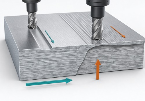
For rolled plate, engineers commonly describe three material directions:
– **Longitudinal (L):** parallel to the principal rolling direction.
– **Long-transverse (LT):** across the plate width, perpendicular to the rolling direction but still in the plate plane.
– **Short-transverse (ST):** through the plate thickness.
These labels describe material orientation, not the X, Y, and Z axes of a CNC machine. A drawing datum or machine axis may coincide with an L, LT, or ST direction, but only if the raw stock is intentionally oriented that way.
Why Does Grain Direction Matter?
Wrought aluminum is **anisotropic**, meaning some properties vary with direction. The degree of anisotropy depends on the alloy, temper, product form, thickness, and production route. It should not be assumed from the alloy number alone.
In many rolled products, longitudinal properties differ from long-transverse and short-transverse properties. Differences may appear in:
– tensile and yield strength;
– elongation and ductility;
– fracture toughness;
– fatigue and crack-growth behavior;
– resistance to stress-corrosion cracking;
– response to forming;
– distortion after material removal.
This does not mean every CNC feature must run parallel to the grain. It means grain orientation becomes an engineering input when a part is structural, thin, highly stressed, or sensitive to dimensional movement.
Does Cutting Parallel to the Grain Machine Better?
There is no universal rule that parallel cutting is always better or that cross-grain cutting is always worse.
During CNC milling, cutting behavior is dominated by the alloy and temper, cutter geometry, edge sharpness, spindle speed, chip load, radial and axial engagement, tool runout, coolant or air delivery, and workholding rigidity. Grain direction can influence the local way material shears, especially at edges or in products with a pronounced directional structure, but it is only one variable.
If a finish differs between two toolpath directions, the correct response is to test under controlled conditions. Keep the tool, feeds, speeds, engagement, workholding, and inspection method constant. Then compare roughness, burr height, waviness, and dimensional results. A visual comparison alone can be misleading because reflected light makes tool marks look different depending on their direction.
### Surface finish
Grain orientation may contribute to small differences in shearing behavior or edge breakout, but obvious chatter, smearing, built-up edge, or torn material usually points first to tool condition and cutting parameters. A sharp, polished aluminum-specific cutter and stable chip evacuation typically matter more than simply rotating the part.
### Burr formation
Burr size can change around the perimeter because an exit edge is approached from different directions. Grain direction may add to this directional effect. Toolpath planning should therefore consider both cutter exit direction and the material’s worked orientation when a part has delicate edges or intersecting holes.
### Tool life
For common wrought aluminum alloys, grain direction alone is rarely the primary driver of tool life. Abrasive constituents, built-up edge, recutting chips, runout, heat, and unsuitable cutter geometry normally have greater influence. If tool wear changes by direction, verify that tool engagement and chip evacuation are genuinely equivalent before attributing the difference to grain.
How Does Grain Direction Affect Part Distortion?
Distortion is often the most important machining consequence.
Rolled plate contains residual stresses from deformation, heat treatment, stretching, flattening, and quenching. These stresses can remain balanced while the stock is intact. Removing a large pocket from one side changes that balance. The part may bow, twist, or move as soon as the clamps are released.
Grain direction and residual stress are related to the stock’s manufacturing history, but they are not identical. A visible or documented rolling direction does not reveal the full residual-stress field. For that reason, the most reliable strategy combines stock selection, balanced machining, process control, and inspection after unclamping.
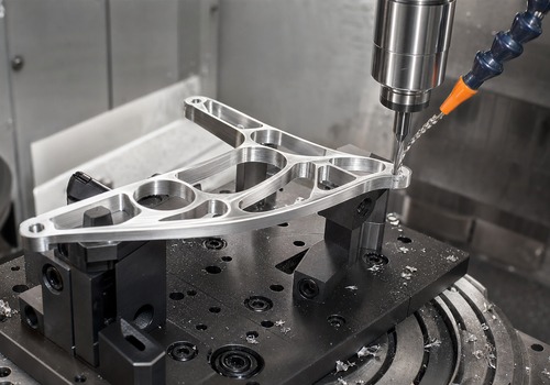
Distortion risk increases when a part has:
– a large amount of material removed from one face;
– deep pockets and a thin floor;
– asymmetric ribs or walls;
– a high length-to-thickness ratio;
– tight flatness, parallelism, or profile requirements;
– aggressive clamping on a flexible section;
– insufficient time between roughing and finishing;
– stock with a residual-stress condition unsuited to the geometry.
Practical ways to reduce movement
1. **Choose appropriate stock.** For precision plate work, discuss residual-stress-controlled or stress-relieved product forms with the material supplier rather than specifying only alloy and temper.
2. **Remove material symmetrically.** Alternate faces when possible and avoid completing one side while the opposite side remains heavy.
3. **Rough first, finish later.** Leave a controlled machining allowance, release the part, allow it to stabilize, then re-fixture for semi-finishing and finishing.
4. **Use low-stress workholding.** Support the component without forcing it flat and creating a spring-back condition after unclamping.
5. **Maintain uniform cutting forces.** Sharp tools and consistent engagement reduce heat and deflection.
6. **Inspect in a free state.** Flatness measured while a flexible part is clamped may not represent its released condition.
7. **Plan a trial part.** For a new high-removal geometry, use the first part to validate stock orientation, setup sequence, and inspection timing.
How Should Designers Orient a Part in the Plate?
The preferred orientation is driven primarily by service requirements, not machining convenience.
If a bracket carries its main tensile load along one axis, the engineer may orient the part so the most suitable material direction follows that load path. If cracks could initiate at a hole, fillet, notch, or threaded feature, fracture and fatigue behavior may be more important than a small difference in cycle time.
The short-transverse direction deserves special attention in thick plate. Through-thickness properties can be less favorable than in-plane properties for some wrought products. Critical features that put the material in through-thickness tension should therefore be reviewed using certified design data for the actual alloy, temper, product form, and thickness.
Questions for the design review include:
– What is the primary service load direction?
– Where are the likely crack-initiation points?
– Does fatigue, fracture toughness, or stress-corrosion resistance control the design?
– Is the part cut from sheet, plate, bar, extrusion, or forging?
– Is the material direction specified on the drawing?
– Can the supplier nest parts while preserving the required orientation?
– Does the orientation create excessive scrap or require a larger blank?
A grain-direction requirement can reduce nesting efficiency and increase material cost. That tradeoff is justified when orientation protects function or safety. It is unnecessary when analysis shows that direction does not affect the application.
What Should Be Specified on the Drawing and RFQ?
If grain direction matters, communicate it explicitly. Do not expect a machine shop to infer the rolling direction from the part shape.
A complete requirement may identify:
– alloy and temper;
– product form, such as rolled plate or extrusion;
– applicable material specification;
– required grain or extrusion direction relative to a datum or feature;
– whether substitutions require written approval;
– material certification and traceability requirements;
– critical mechanical-property direction;
– final inspection requirements after unclamping;
– any stress-relief or stabilization step.
Use an arrow and a clear note tied to a datum or named feature. Avoid vague instructions such as “grain direction as shown” when the drawing does not define the view or material direction unambiguously.
For critical components, request mill certificates that identify the supplied material and applicable specification. When directional properties are essential, the engineering team should verify that the specification and certificate provide the required basis; a generic certificate of conformance may not be enough.
Does Grain Direction Change CNC Programming?
Sometimes, but not automatically.
A programmer may change stock orientation, roughing sequence, finish allowance, toolpath direction, workholding, or inspection pauses. The best plan depends on the part, not on a blanket rule.
A useful process plan for a distortion-sensitive plate component might be:
1. Confirm the marked rolling direction before cutting blanks.
2. Identify each blank so orientation remains traceable through setup.
3. Face both sides lightly to establish stable references.
4. Rough major cavities in balanced stages.
5. Leave stock on critical walls, floors, and datums.
6. Release and re-clamp the part without forcing it flat.
7. Semi-finish, allow stabilization if necessary, and finish critical features.
8. Deburr with attention to edge orientation and thin features.
9. Inspect critical geometry in the condition defined by the drawing.
For high-volume production, record orientation in the setup sheet and fixture design so it does not depend on operator memory.
How Can a Shop Validate the Best Orientation?
When risk is high or data is limited, a small machining trial provides better evidence than assumptions.
Machine representative coupons or first articles in relevant orientations. Record:
– stock identity and orientation;
– setup and clamping method;
– cutting tool and measured runout;
– feeds, speeds, and engagement;
– material removed from each face;
– temperature at machining and inspection;
– flatness or profile before and after unclamping;
– surface roughness by toolpath direction;
– burr location and height;
– dimensional change over time, when relevant.
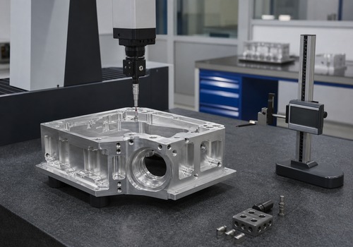
The result becomes process knowledge for later orders. It also helps separate a genuine material-orientation effect from fixture distortion, tool wear, or measurement variation.
Common Mistakes to Avoid
Treating grain direction as cosmetic
Surface streaks or rolling marks can hint at direction, but structural orientation is not merely a cosmetic feature. Confirm it from stock identification or supplier documentation when it matters.
Assuming alloy grade defines behavior
“7075” or “6061” alone does not define product form, temper, thickness, residual stress, or directional properties. Those details belong in the material requirement.
Optimizing nesting before engineering orientation
Rotating parts to fit more pieces on a plate can save material while putting a critical load path in an unintended direction. Resolve orientation before final nesting.
Clamping a warped part flat for inspection
This can hide free-state distortion. The drawing or inspection plan should state the required restraint condition.
Blaming grain direction for every finish problem
First check the cutting edge, runout, parameters, chip evacuation, workholding, and machine condition. Grain direction is one part of a larger machining system.
Key Takeaway
Grain direction in wrought aluminum is most important when it changes **how the finished component carries load or how the stock releases residual stress during machining**. Its direct influence on cutting can be real but is often smaller than the influence of tooling, parameters, chip control, and fixturing.
For robust results:
– orient the part for service performance;
– specify direction only when it is functionally justified;
– choose a suitable product form and residual-stress condition;
– remove material in balanced stages;
– release and re-fixture before final finishing;
– verify the part in the required inspection condition;
– preserve stock-direction traceability through production.
When these decisions are made before quoting, the manufacturer can build grain orientation into material nesting, fixture design, CNC programming, inspection, and cost.
Frequently Asked Questions
### Is aluminum grain direction visible?
Sometimes rolling marks or elongated surface features suggest a direction, but visual appearance is not a reliable method for critical work. Use stock markings and material documentation.
### Is grain direction the same as extrusion direction?
They are related concepts but apply to different product forms. In an extrusion, the primary worked direction follows the extrusion length. In rolled plate, longitudinal direction follows rolling.
### Should a CNC toolpath always follow the aluminum grain?
No. Toolpath direction should be selected using cutting forces, tool engagement, finish requirements, burr control, geometry, and test results. Service orientation and distortion control are normally more important than a blanket parallel-cutting rule.
### Can rotating a part in the plate reduce distortion?
It may change how the part responds, but rotation alone is not a guaranteed solution because residual stress varies through the stock. Stock condition, balanced roughing, workholding, stabilization, and free-state inspection should be considered together.
### Which direction is weakest in aluminum plate?
There is no universal answer for every property and product. Short-transverse performance can be limiting in some thick wrought products, but engineers should use certified data for the specific alloy, temper, thickness, and governing specification.
### Does grain direction affect anodizing?
Material structure, alloy chemistry, heat treatment, surface preparation, and machining marks can influence appearance. Grain orientation may contribute to visual variation, but it is not the only cause.
### What information should a machine shop receive?
Provide alloy, temper, product form, specification, part orientation relative to the stock, critical property direction, certification needs, inspection condition, and approval rules for substitutions.
## Need Wrought Aluminum Parts with Controlled Orientation?
DO Machining supports custom CNC aluminum components from prototype quantities through repeat production. Send your drawing, 3D model, alloy and temper, expected quantity, critical tolerances, finish, and any grain-direction requirement. Our engineering team can review stock orientation, machining sequence, workholding, and inspection requirements before production.