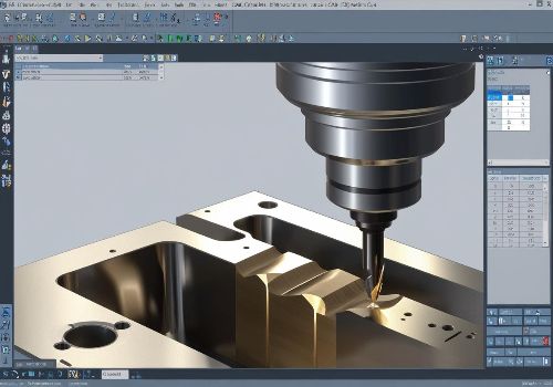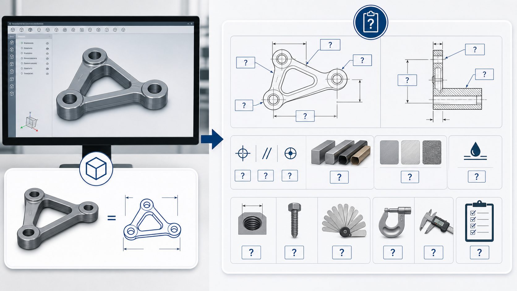
A 3D model is one of the most useful files for CNC part production. It helps the manufacturer understand the shape of the part, review machining feasibility, and prepare CNC programming.
However, a 3D model alone is not always enough for reliable CNC machining. It usually defines geometry, but it may not clearly define how the part should function, how precise it must be, which surfaces are cosmetic, what material should be used, or how the finished part should be inspected.
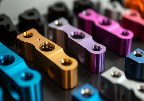
For custom metal parts such as motorcycle brackets, handlebar clamps, foot pegs, risers, spacers, guards, and adapters, these missing details can affect quotation accuracy, production quality, and delivery time.
Why a 3D Model Is Important
A 3D model helps CNC manufacturers understand the physical shape of a part. It is especially useful for complex surfaces, pockets, curved profiles, and multi-axis machining features.
Common 3D file formats include:
- STEP / STP
- IGES / IGS
- Parasolid X_T
- Native CAD files when agreed with the supplier
Among these, STEP is widely used because it can be opened by many CAD and CAM systems.
A good 3D model helps with:
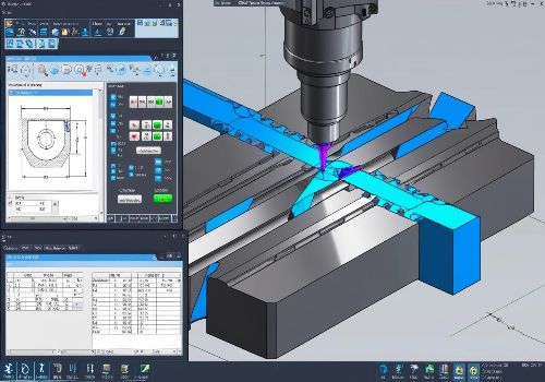
- Machining feasibility review
- Toolpath planning
- Material estimation
- Fixture planning
- Visual communication
- Quotation preparation
But production decisions cannot always be made from geometry alone.
What a 3D Model Usually Does Not Show

A 3D model may show the shape of the part, but it often does not clearly show the manufacturing rules behind that shape.
For example, a 3D model may not define:
- Critical tolerances
- General tolerance standard
- Material grade
- Surface finish
- Thread depth
- Hole function
- Cosmetic surfaces
- Inspection requirements
- Heat treatment
- Coating thickness
- Packaging method
- Revision control
If these details are missing, the supplier may need to ask questions before quoting or producing the part.
1. When Tolerances Are Critical
A 3D model shows nominal dimensions, but it does not always show acceptable variation.
For CNC machining, tolerance is one of the most important production details. A hole position tolerance of ±0.05 mm is very different from a standard tolerance of ±0.20 mm. The tighter tolerance may require better fixturing, slower machining, additional inspection, or special measuring tools.
A 2D drawing should identify:
- Critical dimensions
- General tolerances
- Hole position tolerances
- Flatness requirements
- Parallelism or perpendicularity
- Bearing or bushing fits
- Assembly-critical areas
Without tolerance information, the manufacturer may quote based on standard machining assumptions. This can lead to price changes or production problems later.
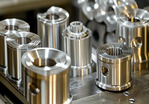
2. When Material Grade Matters
A 3D model does not tell the supplier which material to use.
For example, “aluminum” is not specific enough. Aluminum 6061-T6, 7075-T6, and 5052 have different strength, cost, machinability, and finishing performance.
The same applies to stainless steel and carbon steel.
A proper CNC production package should state:
- Exact material grade
- Material standard, if required
- Whether equivalent material is acceptable
- Heat treatment requirement
- Material certificate requirement
For motorcycle parts exposed to vibration, load, weather, or heat, material selection is not just a purchasing detail. It directly affects product performance.
3. When Surface Finish Is Required
A 3D model normally does not define the final appearance of the part.
For CNC machined metal parts, common surface finishes include:
- Clear anodizing
- Black anodizing
- Hard anodizing
- Powder coating
- Brushing
- Polishing
- Bead blasting
- Zinc plating
- Passivation
- Laser marking
If a buyer only sends a 3D model, the supplier may not know whether the part should be shipped as-machined or finished.
Surface finish requirements should also clarify:
- Color
- Texture
- Cosmetic surfaces
- Areas that must be masked
- Thread protection
- Surface roughness
- Coating thickness
- Acceptable tool marks
This is especially important for visible aftermarket motorcycle parts, where appearance can be as important as function.

4. When Threads and Holes Need Exact Details
A 3D model may show a hole, but it may not clearly show whether the hole is threaded, reamed, countersunk, counterbored, or used for assembly.
For production, the drawing should define:
- Thread size
- Thread pitch
- Thread depth
- Through hole or blind hole
- Counterbore size
- Countersink angle
- Insert requirement
- Chamfer requirement
For example, “M8 hole” is not enough. A better note is:
M8 × 1.25, 15 mm full thread depth
Clear thread and hole details help avoid machining errors and assembly problems.
5. When Inspection Requirements Are Needed
A 3D model does not tell the supplier how the part should be inspected.
Some parts only need standard dimensional checks. Others may require full inspection reports, material certificates, surface treatment certificates, or first article inspection.
Inspection requirements may include:
- Standard dimensional inspection
- First article inspection report
- Full dimensional report
- Material certificate
- Coating thickness report
- Hardness test
- Surface finish measurement
- Inspection photos
- Custom inspection form
If inspection requirements are not provided before production, they may cause delays or additional cost later.
6. When the Part Has Cosmetic Surfaces
For many custom CNC parts, some surfaces are functional while others are cosmetic.
A 3D model does not always identify which surfaces must look clean after machining or finishing.
For visible motorcycle parts such as handlebar clamps, foot pegs, license plate holders, engine covers, side panels, or risers, cosmetic requirements should be clearly marked.
The drawing or RFQ should state:
- Which surfaces are visible after assembly
- Whether tool marks are acceptable
- Required polishing or brushing direction
- Anodizing color requirement
- Scratch protection requirement
- Packaging method
Without this information, the supplier may choose a standard process that meets dimensional requirements but does not meet appearance expectations.
7. When Welding, Bending, or Assembly Is Involved
A 3D model may show the final shape of a part, but it may not fully describe the manufacturing sequence.
For parts involving sheet metal fabrication, bending, welding, or assembly, extra drawings are often required.
The supplier may need:
- Flat pattern drawing
- Bend radius
- Bend direction
- Weld position
- Weld size
- Assembly drawing
- Bill of materials
- Hardware requirements
- Post-weld finishing requirement
This is important for brackets, skid plates, battery boxes, heat shields, chain guards, and adventure motorcycle protection parts.
8. When Revision Control Is Important
A 3D model is not enough if the supplier cannot confirm which version is correct.
Production files should have clear revision control. The 3D model, 2D drawing, and RFQ summary should all match.
Recommended file naming:
PartNumber_PartName_RevB_STEP.stp
PartNumber_PartName_RevB_Drawing.pdf
PartNumber_PartName_RevB_RFQ.xlsx
Revision control helps avoid quoting or producing an outdated version.

What Should Be Sent Together With a 3D Model?
For reliable CNC part production, send a complete production package instead of only a 3D model.
A useful package should include:
- 3D CAD model
- 2D PDF engineering drawing
- Material grade
- Quantity
- Surface finish
- Critical tolerances
- Thread and hole details
- Inspection requirements
- Packaging requirements
- Application information
- Revision number
- Delivery requirement
This helps the manufacturer quote more accurately, reduce technical questions, and prepare production with fewer risks.
Example: CNC Motorcycle Bracket Production
For a CNC machined aluminum motorcycle mounting bracket, a 3D model may show the part shape clearly. But production still needs additional information.
The supplier may need to know:
- Is the material 6061-T6 or 7075-T6?
- Are the mounting holes position-critical?
- Should the part be black anodized?
- Are threads required?
- Which surface is cosmetic?
- Is the part for prototype or batch production?
- Does the buyer need an inspection report?
- Should each part be individually packed?
Without these answers, the supplier can only make assumptions. Assumptions increase the risk of wrong pricing, production delay, or quality disputes.
Quick Checklist: When a 3D Model Is Not Enough
A 3D model is not enough when the part has:
- Tight tolerances
- Threaded holes
- Press-fit or bearing features
- Cosmetic surfaces
- Anodizing, powder coating, brushing, or polishing
- Heat treatment
- Welding or bending
- Assembly requirements
- Inspection report requirements
- Packaging requirements
- Multiple revisions
- Functional or safety-critical application
In these cases, a 2D drawing and RFQ notes should be provided.
FAQ
Is a 3D model enough for a CNC machining quote?
A 3D model may be enough for a rough estimate, but it is usually not enough for a final production quote if the part has tolerances, threads, material requirements, surface finish, or inspection needs.
Why do CNC manufacturers ask for a 2D drawing?
A 2D drawing defines production details that may not be included in the 3D model, such as tolerances, thread depth, material grade, surface finish, and inspection requirements.
What file format is best for CNC machining?
STEP or STP is commonly used for CNC machining because it is compatible with many CAD and CAM systems. A PDF drawing should usually be sent with the STEP file.
Can a supplier manufacture from only a STEP file?
Sometimes yes, for simple non-critical parts. However, the supplier may need to make assumptions. For accurate production, a STEP file should be supported by a 2D drawing and RFQ details.
What information helps reduce CNC quote delays?
Clear material grade, quantity, tolerances, finish, thread details, inspection requirements, packaging, and delivery expectations help reduce quote delays.
Conclusion
A 3D model is essential for CNC part production, but it does not always provide enough manufacturing information. It defines geometry, not necessarily tolerance, material, finish, inspection, packaging, or functional requirements.
For custom CNC machined metal parts, the best approach is to send both a 3D model and a clear 2D drawing. This helps the supplier understand the part correctly, quote accurately, and manufacture with fewer risks.
If you need custom CNC machined motorcycle parts such as brackets, foot pegs, handlebar clamps, risers, spacers, adapters, guards, or covers, preparing a complete production package is the first step toward faster quotation and more reliable production.